Rockwell Automation Publication 20P-TD001K-EN-P - January 2021 59
PowerFlex DC Drive and Field Controller Technical Data
PowerFlex DC Drive and Field Controller Control Power Circuit Protection Fuses
The following fuses are used to protect the switching power supply circuit.
Frame A Switching Power Supply Fuse Location (on all PowerFlex DC Drives and Field Controllers)
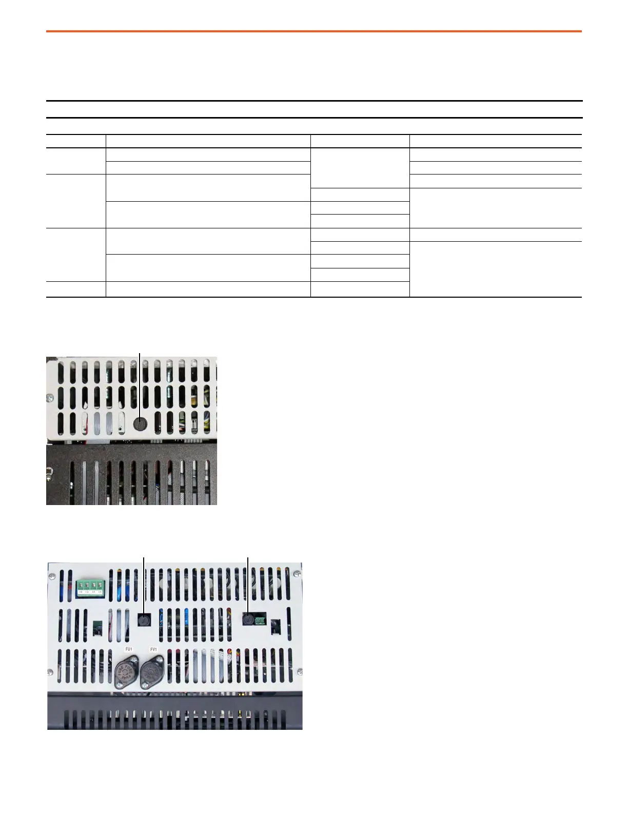
Frame B Switching Power Supply Fuse Location (on all PowerFlex DC Drives and Field Controllers)
IMPORTANT Before you order and install fuses, verify the circuit board revision.
Frame Circuit Board ID / Revision Designation Fuse (5 x 20 mm)
A
SW1-31 / H and below
F1
1 A, 250V, slow
SW1-31 / I and above 2.5 A, 250V, slow
B
SW2-32 / H and below
3.15 A, 250V fast
F2
2.5 A, 250V slow
SW2-32 / I and above
F1
F2
C
(1)
(1) These fuses apply only to PowerFlex DC drives.
SW3-32 / H and below
F1 3.15 A, 250V fast
F2
2.5 A, 250V slow
SW3-32 / I and above
F1
F2
D
(1)
SW1-31 / I and above F1
Top View of Drive
Switching power supply fuse
Top View of Drive F1 = 3.15 A fuse
(Board Rev. “H” and below only)
F2 = 2.5 A fuse
(Board Rev. “H” and below only)

 Loading...


