26 Rockwell Automation Publication PFLEX-AP005A-EN-P - October 2010
Chapter 1 Drive Selection Considerations
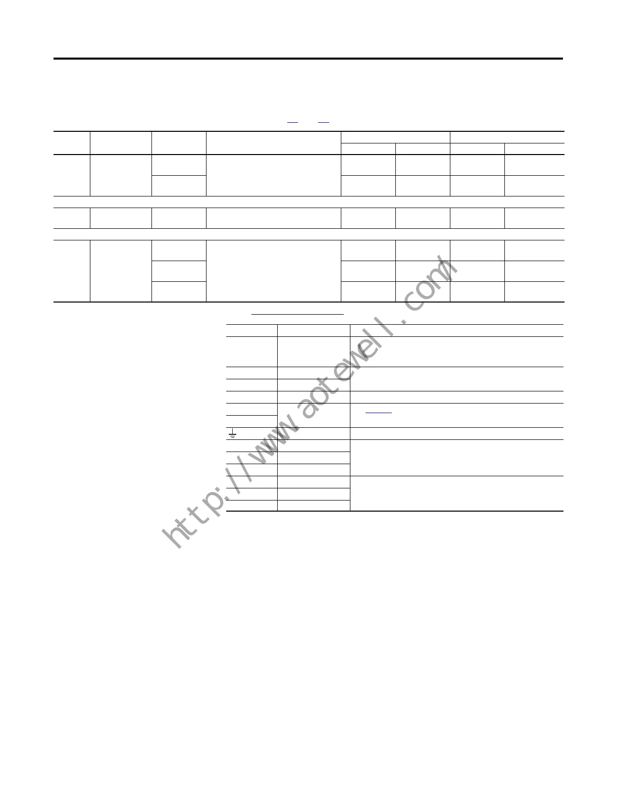
Table 8 - PowerFlex 700 Drives Power Terminal Block Locations (continued)
Refer to pages 27 and 28 for typical locations.
Location
No. Name Frame Description
Wire Size Range
(1)
Torque
Maximum Minimum Maximum Recommended
➍
I/O Terminal
Block
0…6 Signal & control connections 2.5 mm
2
(14 AWG)
0.30 mm
2
(22 AWG)
0.6 N•m
(5.3 lb.•in.)
0.6 N•m
(5.3 lb.•in.)
7…10 4.0 mm
2
(12 AWG)
0.049 mm
2
(30 AWG)
0.6 N•m
(5.3 lb.•in.)
0.6 N•m
(5.3 lb.•in.)
➎
Encoder Terminal
Block
0…10 Encoder power & signal connections 0.75 mm
2
(18 AWG)
0.196 mm
2
(24 AWG)
0.6 N•m
(5.3 lb.•in.)
0.6 N•m
(5.3 lb.•in.)
➏
Fan Terminal
Block
5…6 User supplied fan voltage 4.0 mm
2
(12 AWG)
0.5 mm
2
(22 AWG)
0.6 N•m
(5.3 lb.•in.)
0.6 N•m
(5.3 lb.•in.)
7 4.0 mm
2
(12 AWG)
0.5 mm
2
(22 AWG)
0.9 N•m
(8.0 lb.•in.)
0.6 N•m
(5.3 lb.•in.)
8…10 4.0 mm
2
(12 AWG)
0.5 mm
2
(22 AWG)
0.6 N•m
(5.3 lb.•in.)
0.6 N•m
(5.3 lb.•in.)
(1) Maximum/minimum sizes that the terminal block will accept—these are not recommendations.
Terminal Description Notes
BR1
BR2
DC Brake (+)
DC Brake (–)
DB Resistor Connection
Important: Only one DB resistor can be used with Frames 0…3.
Connecting an internal & external resistor could cause damage.
DC+ DC Bus (+) DC input/brake connections
DC– DC Bus (–)
PE PE Ground
PS+ Auxiliary Control
Terminal Block
see page 27
PS–
Motor Ground
U U (T1) To motor
VV (T2)
WW (T3)
R R (L1) AC line input power
Three-phase = R, S & T
Single-phase = R & S only
(1)
SS (L2)
T T (L3)
(1) Frames 0…7 only.
 Loading...


