Rockwell Automation Publication PFLEX-AP005A-EN-P - October 2010 33
Drive Selection Considerations Chapter 1
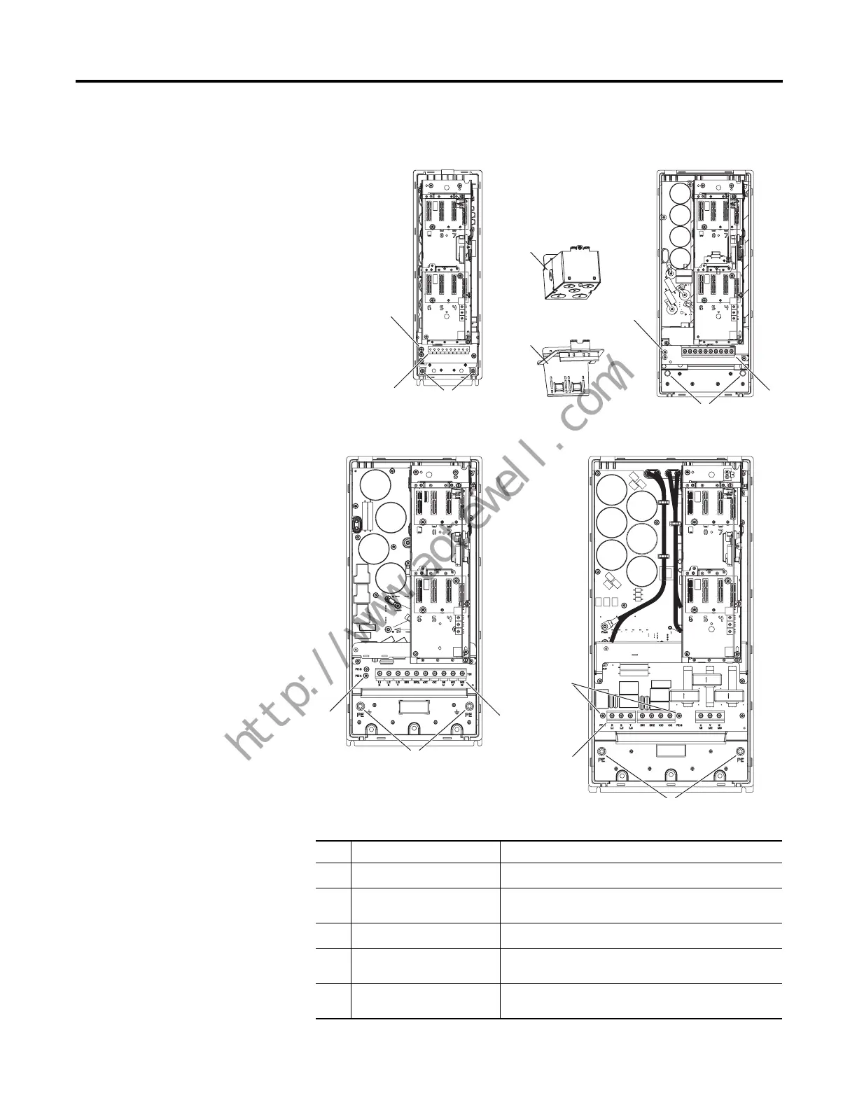
Figure 16 - PowerFlex 750-Series Frames 2…5
Typical Terminal Block Location and Termination Points
No. Name Description
➊
Power Terminal Block R/L1, S/L2, T/L3, BR1, BR2, +DC, -DC, U/T1, V/T2, W/T3
➋
PE Grounding Studs Terminating point to chassis ground for incoming AC line
and motor shields
➌
PE-A and PE-B MOV and CMC jumper screws
➍
Optional NEMA/UL Type 1
Conduit Box
Terminating point to chassis ground for incoming AC line,
motor shields, and control wire shields
➎
Optional EMC Plate Terminating point to chassis ground for incoming AC line,
motor shields, and control wire shields
➊
➊
➊
➌
➊
➌
➋
➌
➍
➎
➋
➌
➋
➋
Frame 2
Frame 3
Frame 4
Frame 5
 Loading...


