34 Rockwell Automation Publication PFLEX-AP005A-EN-P - October 2010
Chapter 1 Drive Selection Considerations
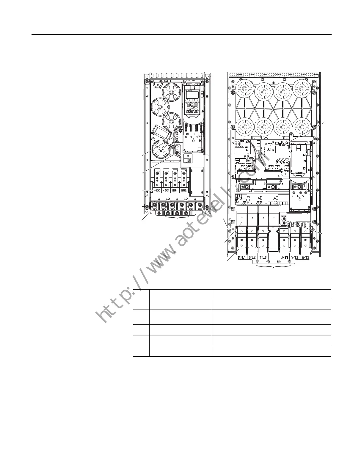
Figure 17 - PowerFlex 750-Series Frames 6 & 7
Typical Terminal Block Location and Termination Points (continued)
No. Name Description
➊
Power Terminals R/L1, S/L2, T/L3, U/T1, V/T2, W/T3
➋
PE Grounding Studs Terminating point to chassis ground for incoming AC line
and motor shield
➌
DC Bus and Brake Terminals +DC, -DC, BR1, BR2
➍
PE-A and PE-B MOV and CMC jumper wires
➎
DC+ and DC- Bus voltage test points
➌
➎
➍
➊
➋
➍
➋
➊
➌
➎
➍
➍
Frame 6
Frame 7
 Loading...


