Rockwell Automation Publication PFLEX-AP005A-EN-P - October 2010 35
Drive Selection Considerations Chapter 1
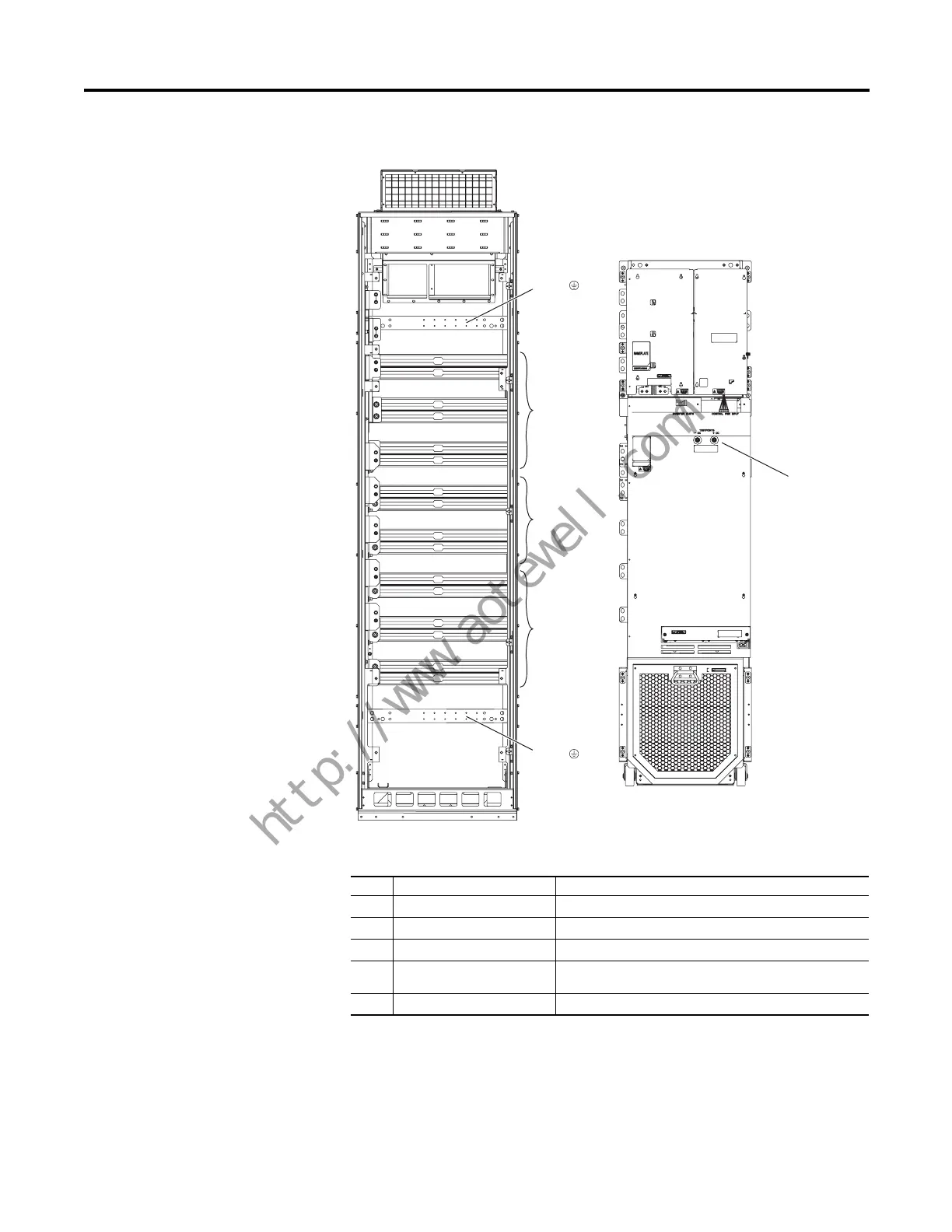
Figure 18 - PowerFlex 755 Drive Power Terminal Bus Bar Locations
Table 14 - PowerFlex 755 Drive Frame 8 Power Terminal Locations
No. Name Description
➊
Power Bus R/L1, S/L2, T/L3
➋
DC Bus DC+, DC- (requires field installed kit 20-750-BUS1-F8)
➌
Power Bus U/T1, V/T2, W/T3
➍
PE Grounding Bar Terminating point to chassis ground for incoming AC line and
motor shield
➎
DC+ and DC- Bus voltage test points
➋
➊
➌
➍
➍
➎
R / L1
S / L2
T / L3
DC+
DC-
U / T1
V / T2
W / T3
PE
PE
Frame 8
 Loading...


