EasyManuals Logo

Rockwell Automation Allen-Bradley PowerFlex 750 Series User Manual

Rockwell Automation Allen-Bradley PowerFlex 750 Series
40 pages
To Next Page IconTo Next Page
To Previous Page IconTo Previous Page
Page #23 background imageLoading...
Page #23 background image
Rockwell Automation Publication 750-UM002H-EN-P - February 2017 23
Installation and Wiring Chapter 2
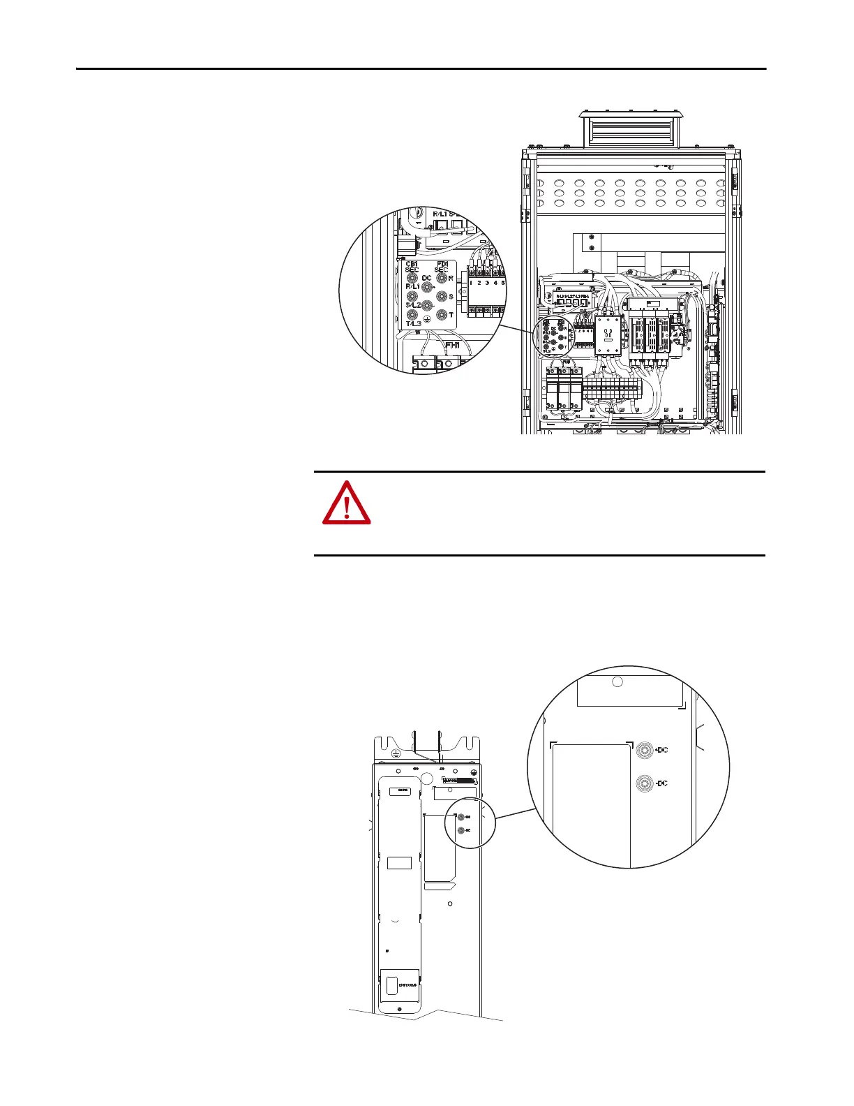
4. For common-bus inverters, measure the DC-bus voltage of all power
modules and verify that there is no voltage present on the bus capacitors.
Measure +DC to -DC, +DC to chassis GND, and -DC to chassis GND
using the DC bus testpoints +DC and -DC.
ATTENTION: To avoid an electric shock hazard, verify that the voltage on the
bus capacitors has discharged completely before servicing. Verify that there
is no DC bus voltage present using the +DC to -DC testpoints on all power
modules by measuring +DC to -DC, +DC to GND, and -DC to GND.
Frame 9, IP21 UL Type 1 Input Bay Shown

Other manuals for Rockwell Automation Allen-Bradley PowerFlex 750 Series

Questions and Answers:

Question and Answer IconNeed help?

Do you have a question about the Rockwell Automation Allen-Bradley PowerFlex 750 Series and is the answer not in the manual?

Rockwell Automation Allen-Bradley PowerFlex 750 Series Specifications

General IconGeneral
BrandRockwell Automation
ModelAllen-Bradley PowerFlex 750 Series
CategoryDC Drives
LanguageEnglish

Related product manuals