30 Rockwell Automation Publication 750-UM002H-EN-P - February 2017
Chapter 3 Safe Torque Off Option Module Operation
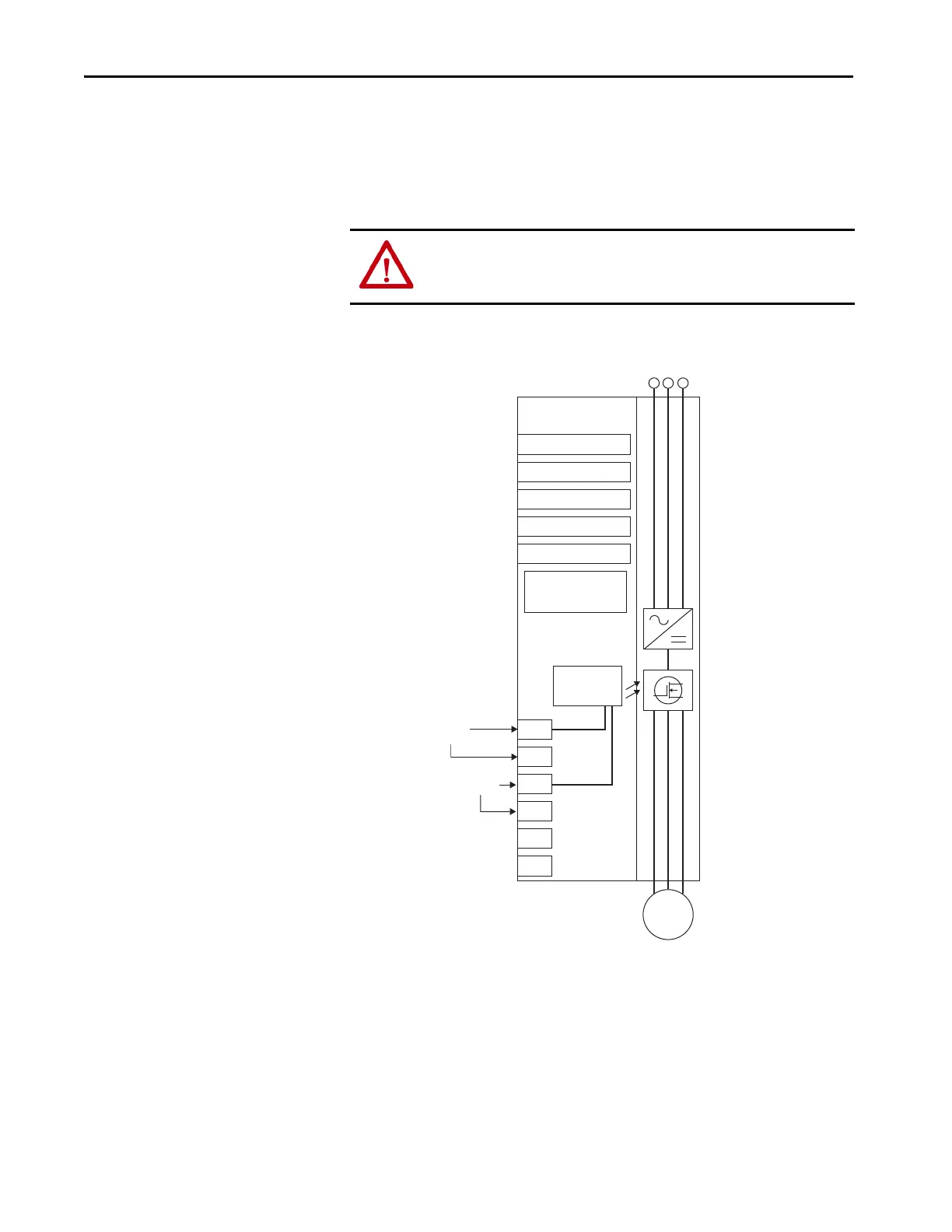
Under normal operation, 24V DC is applied to both the Safety Power and
Safety Enable inputs of the safety option module. If the Safety Enable or Safety
Power is de-energized, the outputs of the gate-control driver IC are disabled
and IGBT firing is disabled. Parameter 933 [Start Inhibits] indicates that
IGBTs are inhibited and the HIM indicates that the drive is not enabled.
Figure 5 - Drive Safe Torque Off Circuitry
Stop Category Wiring
Examples
The following diagrams illustrate Stop Category 0 and Stop Category 1 dual-
channel wiring examples for PowerFlex 750-Series drives with Guardmaster®
safety relays. Examples include the following drive families:
• PowerFlex 753 and PowerFlex 755 Drives, Frames 1…10
• PowerFlex 755T Drive Products, Frames 8…12
ATTENTION: By itself, the safety option module initiates a coast-to-stop
action. Additional protective measures must be applied when an application
requires a different stopping action.
SP+
SE+
Sd
SP–
SE–
Sd
AC Line
Input Power
PowerFlex 750-Series
AC Drives
+24V DC
Stop
Start
Start/Stop Common
24V DC Common
Jumpers:
ENABLE Installed
SAFETY Removed
Gate Control
Safety
Power
Safety
Enable
Motor

 Loading...


