16 Rockwell Automation Publication 750-UM002H-EN-P - February 2017
Chapter 2 Installation and Wiring
Access the Drive Control Pod
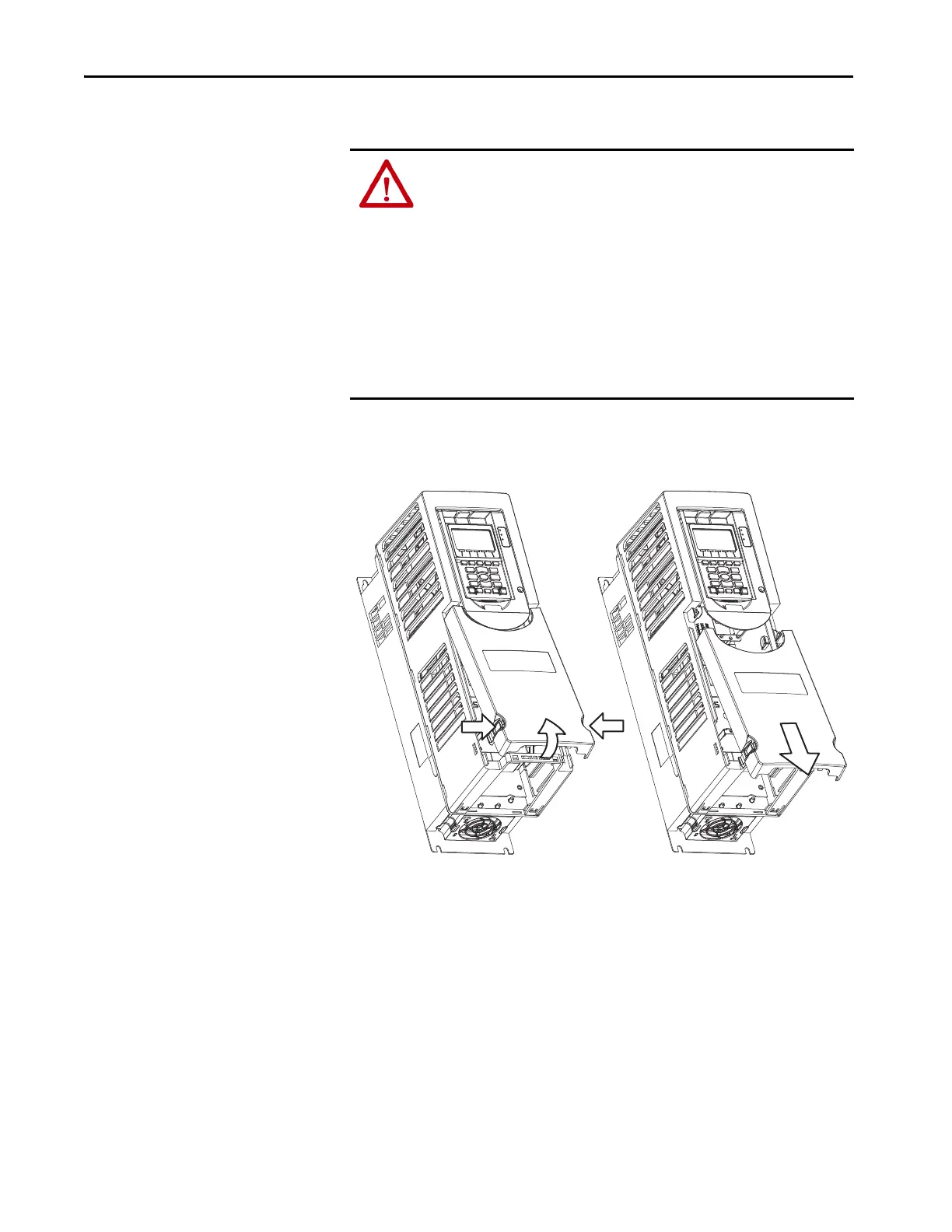
Follow these steps to remove the drive covers and access the enable jumpers.
1. Remove drive cover.
PowerFlex 755 and PowerFlex 753 Drives, Frames 1…5
a. Squeeze locking tabs and pull out bottom of cover.
b. Pull cover down and away from the chassis
ATTENTION:
• Electrical Shock Hazard. Verify that all sources of AC and DC power are de-
energized and locked out or tagged out in accordance with the requirements
of ANSI/NFPA 70E, Part II.
• To avoid an electric shock hazard, verify that the voltage on the bus
capacitors has discharged before performing any work on the drive. Measure
the DC bus voltage at the +DC and -DC terminals or test points (refer to your
drive’s user manual for locations). The voltage must be zero.
• In Safe Torque Off mode, hazardous voltages may still be present at the
motor. To avoid an electric shock hazard, disconnect power to the motor and
verify that the voltage is zero before performing any work on the motor.

 Loading...


