20 Rockwell Automation Publication 750-UM002H-EN-P - February 2017
Chapter 2 Installation and Wiring
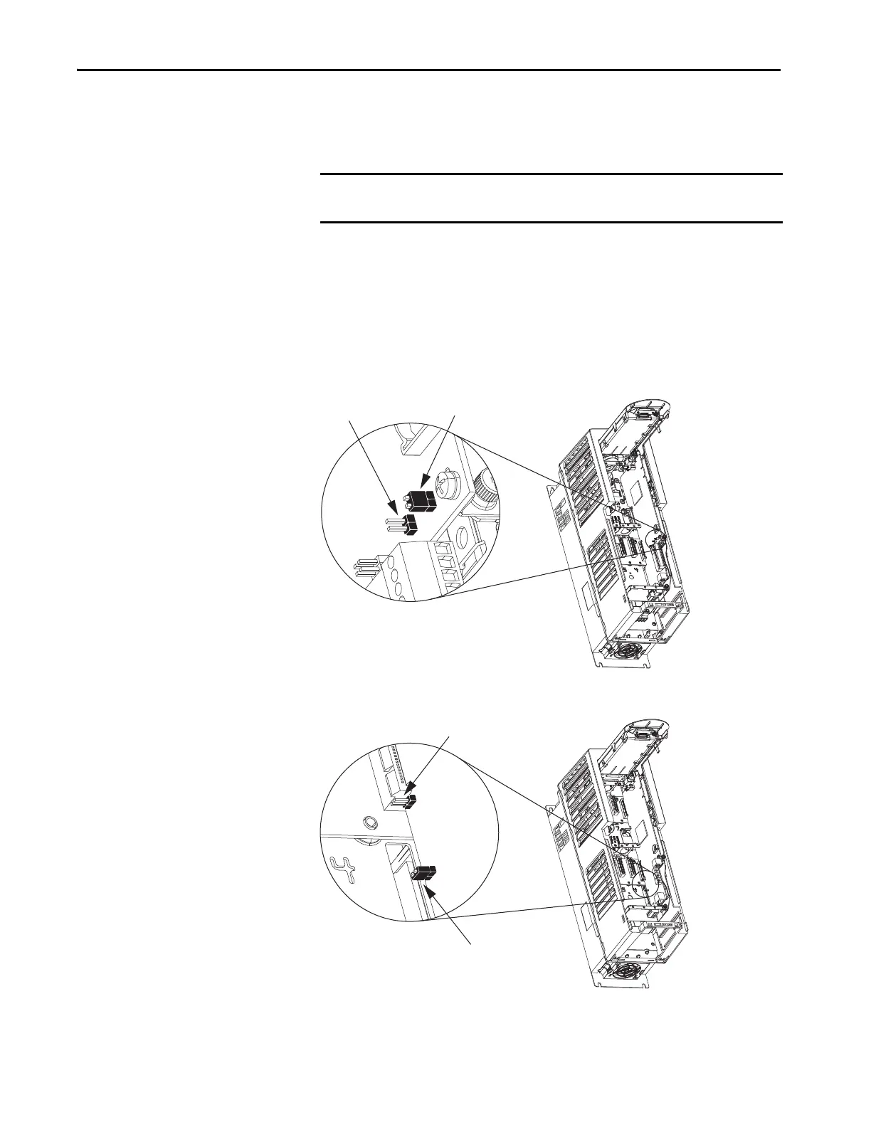
Set the Safety Enable Jumper
The PowerFlex 750-Series drives ship with the safety-enable (SAFETY)
jumper installed. The jumper, located on the main control board, must be
removed when using the Safe Torque Off option module.
The Di0 digital output on the main control board can be designated as a
Hardware Enable function by removing the hardware ENABLE jumper. If this
jumper is removed, the drive will not run unless the Di0 digital input is
activated. The Di0 input is not related to the operation of the safety option
module. If you are not using the Di0 input as Hardware Enable, do not remove
the hardware ENABLE jumper.
Figure 2 - PowerFlex 753 Drive Jumper Locations
Figure 3 - PowerFlex 755 Drive Jumper Locations (frames 1…7 only)
PowerFlex 755 drives (frame 8, 9, and 10) do not have a safety enable jumper.
IMPORTANT Failure to remove the SAFETY jumper causes the drive to fault when a start
command is issued.
PowerFlex 753 AC Drive
SAFETY Enable
(jumper removed)
Hardware ENABLE (jumper in place)
PowerFlex 755 AC Drive
SAFETY Enable
(jumper removed)
Hardware ENABLE (jumper in place)

 Loading...


