Rockwell Automation Publication 750-UM002H-EN-P - February 2017 25
Installation and Wiring Chapter 2
Wire the Safety Option
Module
Observe these wiring guidelines when installing the safety option module:
• Use copper wire with an insulation rating of 600V or greater is
recommended.
• Separate control wires from power wires by at least 0.3 m (1 ft).
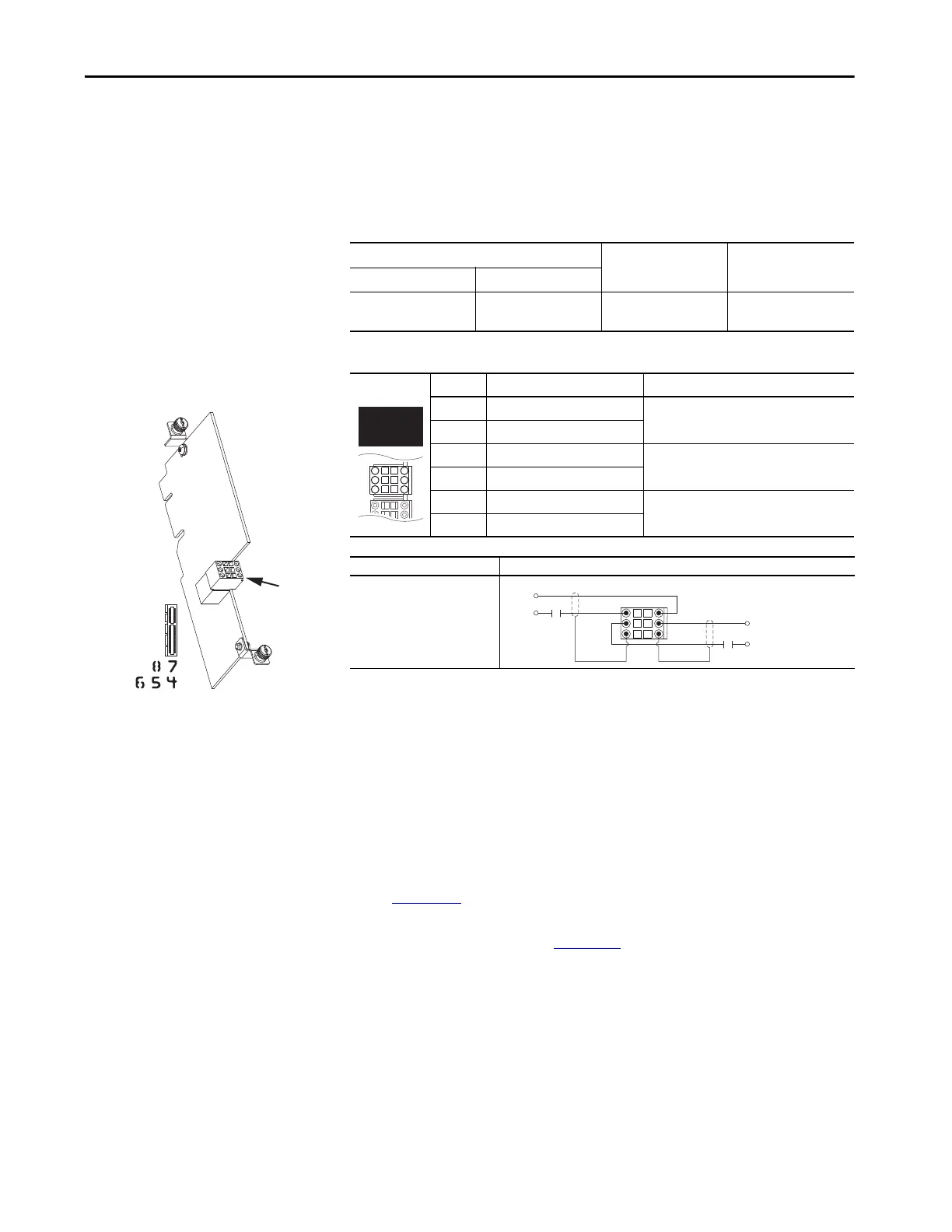
Table 4 - Safety Option Module Terminal Block Specifications
Table 5 - TB2 Terminal Designations
Cabling
Safety input wiring must be protected against external damage by cable
ducting, conduit, armored cable or other means.
Shielded cable is required. For proper shield termination, follow the
installation requirements related to EN 61800-3 and the EMC Directive as
described in these publications:
• PowerFlex 750-Series AC Drive Installation Instructions, publication
750-IN001
• PowerFlex 750-Series Products with TotalFORCE™ Control Installation
Instructions, publication
750-IN100
Wire Size Range
Wire Type Strip Length
Maximum Minimum
0.8 mm
2
(18 AWG)
0.3 mm
2
(28 AWG)
Multi-conductor shielded
cable
10 mm
(0.39 in.)
Terminal Name Description
SP+ +24 Volt Safety Power
User-supplied power: 24 volt ±10%
45 mA typical
SP- Safety Power Common
SE+ +24 Volt Safety Enable
User-supplied power: 24 volt ±10%
25 mA typical
SE- Safety Enable Common
Sd Shield
Terminating point for wiring shields when an
EMC plate or conduit box is not installed.
Sd Shield
Safety Input Connection Example
Power Supply
TB2
20-750-S Safe Torque Off
Option Module
SP+
SE+
Sd
SP-
SE-
Sd
SE-
SP+
SP-
SE+
Sd Sd
Common
+24V
+24V
Common

 Loading...


