Rockwell Automation Publication 750-UM002H-EN-P - February 2017 33
Safe Torque Off Option Module Operation Chapter 3
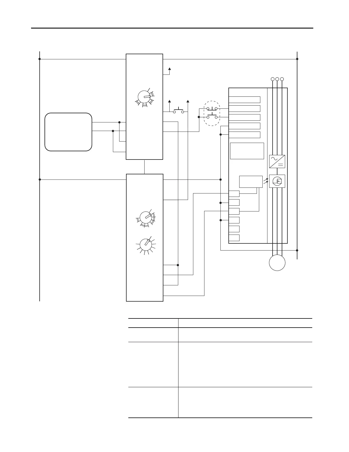
Figure 8 - Stop Category 1
Table 9 - Guardmaster DI and EMD Example Summary
SP+
SE+
Sd
SP–
SE–
Sd
A1
S11
S21
24V DC
0V DC COM
Gray
Pink
24V DC
DI
A2
S12
S22
S32
S42
13
14
23
24
0
1
2
3
4
56
7
8
LOGIC
A1
B1
A2
X32
37
38
47
48
17
18
27
28
1
2
3
4
5
6
7
8
RANGE
10
1
2
3
4
5
6
7
8
TIME
9
0
9
L12
L11
L11
EMD
Y32
S34
AC Line
Input Power
Motor
24V DC COM
START
STOP
PowerFlex 750-Series
Drive
Gate Control
Jumpers:
ENABLE Installed
SAFETY Removed
START/STOP COM
Guardmaster®
440R-D22R2
Dual-input Safety Relay
Guardmaster®
440R-EM4R2D
Expansion Module Delayed
SensaGuard
Interlock Switch
Reset
Aux
(PAC)
Aux
(PAC)
Aux
(PAC)
Attribute Description
Circuit status
Circuit is shown with guard door closed and system ready for normal drive
operation.
Operating principle
This is a dual-channel system with monitoring of the Safe Torque Off circuit and
drive. Opening the guard door switches the input circuits (S12, S22 and S32, S42) to
the Guardmaster monitoring safety relay. The output circuits (13, 14) issue a Stop
command to the drive and cause a controlled deceleration. After the programmed
delay, the timed output circuits (17, 18 and 27, 28) causes the Safe Torque Off
option module and the drive Enable circuit to trip. If the motor is rotating when the
trip occurs, it will coast to stop. To restart the drive, the Guardmaster safety relay
must first be reset followed by a valid start command to the drive.
Fault detection
A single fault detected on the Guardmaster safety input circuits results in the lock-
out of the system at the next operation and does not cause loss of the safety
function.
If the safety option module sticks ON, the motor stops on command due to the
enable input. The system cannot be reset when this fault condition exists.

 Loading...


