12 Rockwell Automation Publication 6200-IN001A-EN-P - October 2019
VersaView 5000 Thin Clients, Industrial Computers, and Accessories for Hazardous Locations
Hardware Features
This section shows the hardware features of VersaView 5000 devices for hazardous locations.
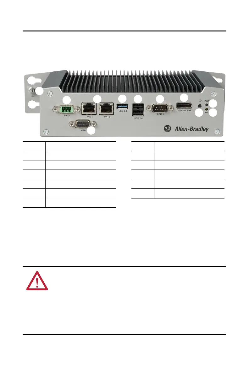
Figure 3 - Hardware Features of VersaView 5000 Devices for Hazardous Locations
Connect Power
VersaView 5000 devices for hazardous locations are factory shipped to be connected to a
12…24V DC power source.
Item Component Item Component
1 12…24V DC power input connection 7 Power light-emitting diode (LED)
2 2 x Ethernet LAN port 8 SSD LED
3 USB 3.0 port 9 Power button
4 2 x USB 2.0 port 10 VGA port
5 Serial COM port, RS-232 11 Ground stud
6DisplayPort
(1)
(1) Audio output/line out supported.
ATTENTION: When you connect power to the VersaView 5000 device for hazardous locations for
the first time, these actions occur:
• The default UEFI setting automatically starts the VersaView 5000 device after it is plugged into
a power source.
• For VersaView 5000 devices with a Windows operating system (OS), you must read and accept
an End User Setup procedure.
Do not disconnect power from the system until after the Windows Setup procedure is
completed. If power is disconnected during this procedure, it can result in a corrupted system
image.
 Loading...