14
Publication 1763-IN001C-EN-P - June 2015
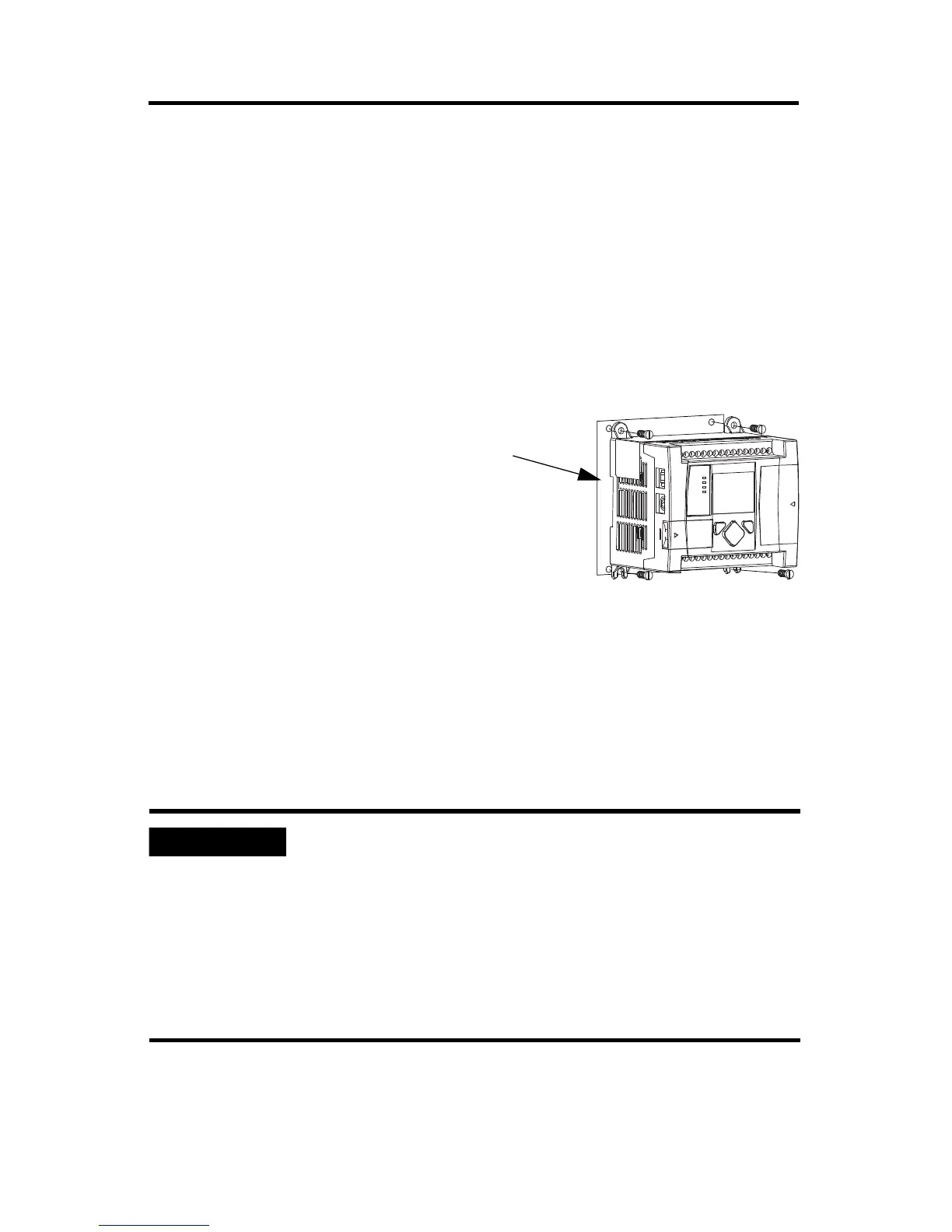
Panel Mounting
Mount to panel using #8 or M4 screws. Follow these steps to install your controller using
mounting screws.
1. Remove the mounting template from inside the back cover of this document.
2. Secure the template to the mounting surface. (Make sure your controller is spaced
properly. See Controller Spacing on page 12.)
3. Drill holes through the template.
4. Remove the mounting template.
5. Mount the controller.
6. Leave the protective debris strip
in place until you are finished
wiring the controller and any
other devices
Using the Battery
The MicroLogix 1100 controller is equipped with a replaceable battery. The Battery Low
indicator on the LCD display of the controller shows the status of the replaceable battery.
When the battery is low, the indicator is set (displayed as a solid rectangle). This means that
either the battery wire connector is disconnected, or the battery may fail within 2 days if it is
connected.
The MicroLogix 1100 controller ships with the battery wire connector connected.
Ensure that the battery wire connector is inserted into the connector port if your
application needs battery power. For example, when using a real-time clock (RTC), or
to store the program in the controller’s memory for an extended period of time while
the power is removed.
Refer to the MicroLogix 1100 Programmable Controller User Manual, publication
1763-UM001, for more information on installation, handling, usage, storage, and
disposal of the battery.
 Loading...


