18
Publication 1763-IN001C-EN-P - June 2015
Wire Requirements
Wiring Recommendation
The MicroLogix 1100 controllers have screw-cage clamps on the input and output terminal
blocks. With screw-cage clamp terminal blocks, there is no need to attach additional hardware
such as a spade lug to the wire, or use a finger-safe cover.
Follow these steps to wire the terminal block.
1. Strip the end of the wire.
The recommended length for the stripped end of the wire is 11.0 mm
(0.440 in.).
Wire Type Wire Size (2 wire maximum per terminal)
1 wire per terminal 2 wire per terminal
Solid Cu-90 °C (194 °F) 12...20 AWG 16...20 AWG
Stranded Cu-90 °C (194 °F) 14...20 AWG 18...20 AWG
Wiring torque = 0.56 Nm (5.0 in-lb) rated.
Be careful when stripping wires. Wire fragments that fall into the controller could
cause damage. Once wiring is complete, be sure the controller is free of all metal
fragments before removing the protective debris strip. Failure to remove the strip
before operating can cause overheating.
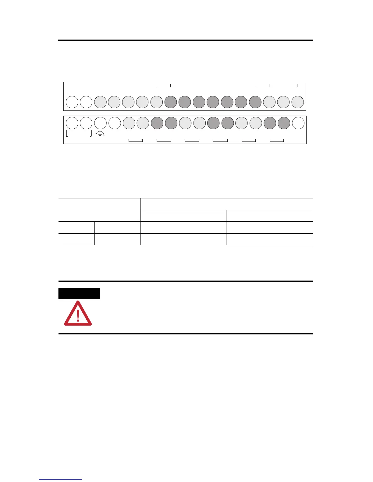
Input Terminal Block
Output Terminal Block
DC
COM
NOT
USED
+ 12/24V -
DC IN
NOT
USED
I/1I/0 I/2 I/3
DC
COM
I/4 I/5
IA
COM
IV1(+) IV2(+)I/6 I/7 I/8 I/9
VAC O/0
VDC
VAC O/1
VDC
VAC O/2
VDC
VAC O/3
VDC
VAC O/4
VDC
VAC O/5
VDC
NOT
USED
NOT
USED
 Loading...


