19
Publication 1763-IN001C-EN-P - June 2015
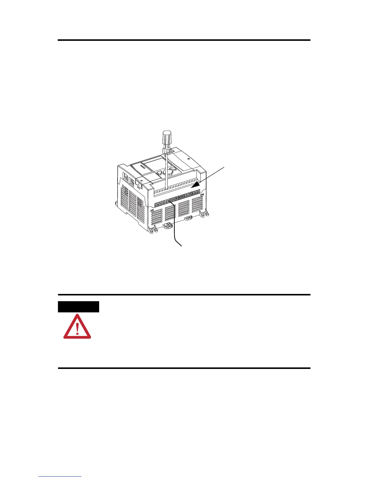
2. Insert it into an open clamp.
3. Using a small, flat-blade screwdriver, tighten the terminal screw. To ensure that the
wire conductor is secured inside the clamp, tighten it to the rated torque, 0.56 Nm (5.0
in-lb).
The diameter of the terminal screw head is 5.5 mm (0.220 in.).
Surge Suppression
Inductive load devices such as motor starters and solenoids require the use of some
type of surge suppression to protect the controller output. Switching inductive loads
without surge suppression can significantly reduce the life of relay contacts or
damage transistor outputs. By using suppression, you also reduce the effects of
voltage transients caused by interrupting the current to that inductive device, and
prevent electrical noise from radiating into system wiring. Refer to the MicroLogix
1100 Programmable Controller User Manual, publication 1763-UM001, for more
information on surge suppression.
Screw-cage clamp terminal block
 Loading...


