21
Publication 1763-IN001C-EN-P - June 2015
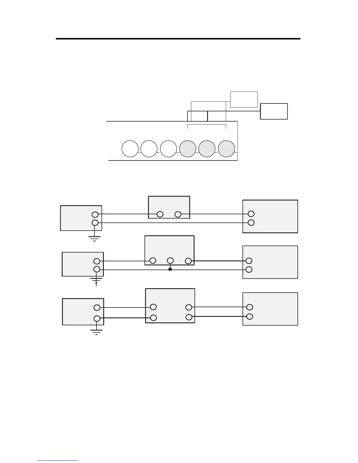
Wiring Your Analog Channels
Analog input circuits can monitor voltage signals and convert them to serial digital data.
The controller does not provide loop power for analog inputs. Use a power supply that
matches the transmitter specifications as shown below.
Minimizing Electrical Noise on Analog Channels
Inputs on analog channels employ digital high-frequency filters that significantly reduce the
effects of electrical noise on input signals. However, because of the variety of applications and
environments where analog controllers are installed and operated, it is impossible to ensure
that all environmental noise will be removed by the input filters.
Several specific steps can be taken to help reduce the effects of environmental noise on
analog signals:
Sensor 2
(V) Voltage
Sensor 1
(V) Voltage
IV1(+) or IV2(+)
IA COM
IV1(+) or IV2(+)
IA COM
+-
+
-
+
-
IV1(+) or IV2(+)
IA COM
+
-
+
-
GND
+
-
TransmitterTransmitter
Transmitter
Transmitter
Supply Signal
Supply Signal
Controller
Controller
Controller
Power
Supply
3-Wire Transmitter
4-Wire Transmitter
2-Wire Transmitter
Power
Supply
Power
Supply
 Loading...


