PR301v2.1UK.doc 02-07-29
3
Note: For networked systems with CPRs the RACS 3.x software is required.
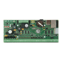
CPR characteristic:
- 250.000 or 64.000 events buffer (CPR32 or CPR8),
- operation with 32 or 8 access controllers (CPR32 or CPR8),
- buffered 2A power supply,
- battery charging control circuit,
- automatic battery cut off circuit below 10V level,
- LED/buzzer signalization panel,
- PGM alarm output,
- TAMPER loop input line,
- metal case with compartment for 17Ah battery.
Building installation above 32 controllers
The separate CPR 32/8 control panel can operate with up to 32/8 controllers. When more door have to be controlled the access system
with multiply subsystems must be utilized (
see diagram
). Every subsystem must have its own CPR panel, UT-2 interface,
communication bus and must be connected to separate PC’s COM port.
Note: Operation with multi subsystems requires RACS 3.x software packet.
Recording of events
In case where controllers operate in a networked mode, the following types of events can be recorded:
• Access granted for …
• Access deny for …
• PIN-code under constrain (DURESS
ENTRY) by user ....
• "PREALARM" condition on …
• „DOOR AJAR” condition on …
• „FORCED ENTRY” condition on …
• Controlled switched to ON or OFF mode by …
• Reporting input no … triggered
• Reporting input no … returned to normal
• RESTART of the controller…
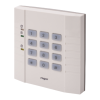
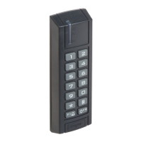
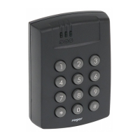
Operation with remote access terminal
One additional access terminal (reader) with ID=0 can be connected to PR301/201 controller. Terminal does not make decision to grant
or deny access, terminal reads user identifier (card code, PIN-code or both) than send it to controller which examine codes and grant or
deny access for recognized user. There are few types of terminals including outdoor versions.
Notice: The roger access terminals (PRT series) utilize clock and data lines for communication with controller but this standard differs
from common CLOCK&DATA format utilized by many producers. Some PRT terminals are also offered with Wiegand and Magstrip
standards but such a types are specially marked.
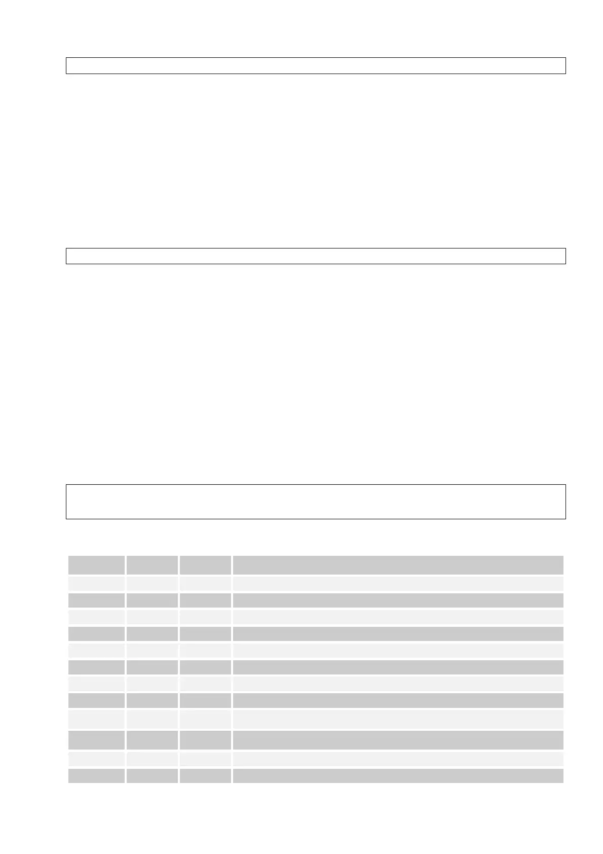
Optical (LED) signalization
LED
ON/OFF
LED
OPEN
LED
SYSTEM
Interpretation.
!R
" "
The controller is in the ON mode.
!G
" "
The controller is in the OFF mode.
" " #
The controller stands by for entering the MASTER or SWITCHER Ident.
" # "
The controller stands by for entering the MASTER Ident.
#R
" "
The controller stands by for entering the INSTALLER Ident.
" ! !
The controller is in the user programming mode.
" # #
Standby for entering the remaining part of the command in the user programming mode.
!R
" !
The controller is in the installer programming mode.
#R
" #
Standby for entering the remaining part of the command in the installer programming
mode.
#R
# #
EEPROM memory data damage, the default settings should be restored and the controller
should be reprogrammed.
#R
# !
The controller is being programmed from PC (Downloading process in progress)
!R/G
! "
The LED’s light up when the door is open.
 Loading...