27
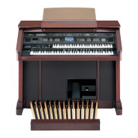
AT-80SL
6. Push Upper Panel to Rear Board and pull up it by rotating it.
fig.80s-09e_50
fig.80s-10e_50
fig.90s-06e_50
Note: Please prevent the cable from a power switch contacts a transformer by
putting it between the coating clip and Side Board after work’s
finishing and closing Upper Panel.
fig.80s-13e_50
7. If you need to remove Upper Keyboard, Remove the 12 screws around it.
(For example, in order to remove a panel board, you need to remove
Upper Keyboard beforehand.)
fig.90s-07e_50
8. Next remove the clamp tie and remove the cable from the connector (CN6
on Panel B Board).
fig.90s-08e_50
fig.90s-09e_50
 Loading...