31
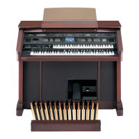
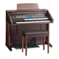
AT-80SL
SK-956 & SK-976 part
2. Aligning the cutouts in the PWB with the lugs on the chassis, put one side
of the PCB into the chassis hooks.
Place the PCB on the chassis so that the chassis positioning pins fit into
the positioning holes. (See fig.3)
At this point, the chassis positioning reference pin should first be fitted
into the hole.
There are two PCBs, LOW and HI, as shown in fig.4.
The chassis positioning reference pins are located near the connector each
of the LOW and HI PCBs.
fig.keyboard-
4e
Lower Keyboard (SK-976 KBD ASSY)
Upper Keyboard (SK-956 KBD ASSY)
Positioning Pin
Cutouts in the PWB
Hook Lug
Positioning Pin
Fig.4
Fig.3
Fig. 4
 Loading...