Installing REAC Devices
27
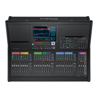
Connecting REAC Input/Output Units
This describes how to connect REAC input/output units to the M-5000
and add audio input and output.
This section shows a typical example of a connection using
the S-2416. For connections of greater complexity, refer to the
Reference Manual (PDF).
S-2416 S-2416
SLAVE SLAVE
REAC A
MASTER
REAC B
MASTER
M-5000
CLOCK SOURCE: INTERNAL
The input/output units connected to the REAC A and B ports and
the default input/output patchbays on the M-5000 are as follows.
Input port Input channel
REAC A INPUT 1–24 CH 1–24
REAC B INPUT 1–24 CH 25–48
CONSOLE INPUT 1–16 CH 49–64
FX 7 OUTPUT L/R CH 65
FX 8 OUTPUT L/R CH 66
DOCK L/R CH 67
PLAY L/R CH 68
Output port Output bus
REAC A OUTPUT 1–16 AUX 1–16
REAC B OUTPUT 1–8 AUX 17–24
REAC B OUTPUT 9-11 MAIN L, R, C
REAC B OUTPUT 12-16 MATRIX 1-5
CONSOLE OUTPUT 1-3 MATRIX 6-8
CONSOLE OUTPUT 4-5 MONITOR 1 L,R
Important Notes on REAC Connections
REAC connections are designed not to produce noise when hot-
swapping (inserting or detaching live lines) is performed. In rare
cases, however, noise might occur in the system's audio output. The
following two methods can prevent damage due to hot-swapping
to speakers or other devices connected to audio outputs.
5 Make the REAC connection while holding down [MUTE ALL
OUTPUTS] on the input/output unit.
5 Go to the MUTE GROUP MASTER window and use [MUTE ALL
OUTPUTS] to mute output, then make the REAC connection.
0“Muting All Outputs” (p. 60))
 Loading...