Part Names and Functions
36
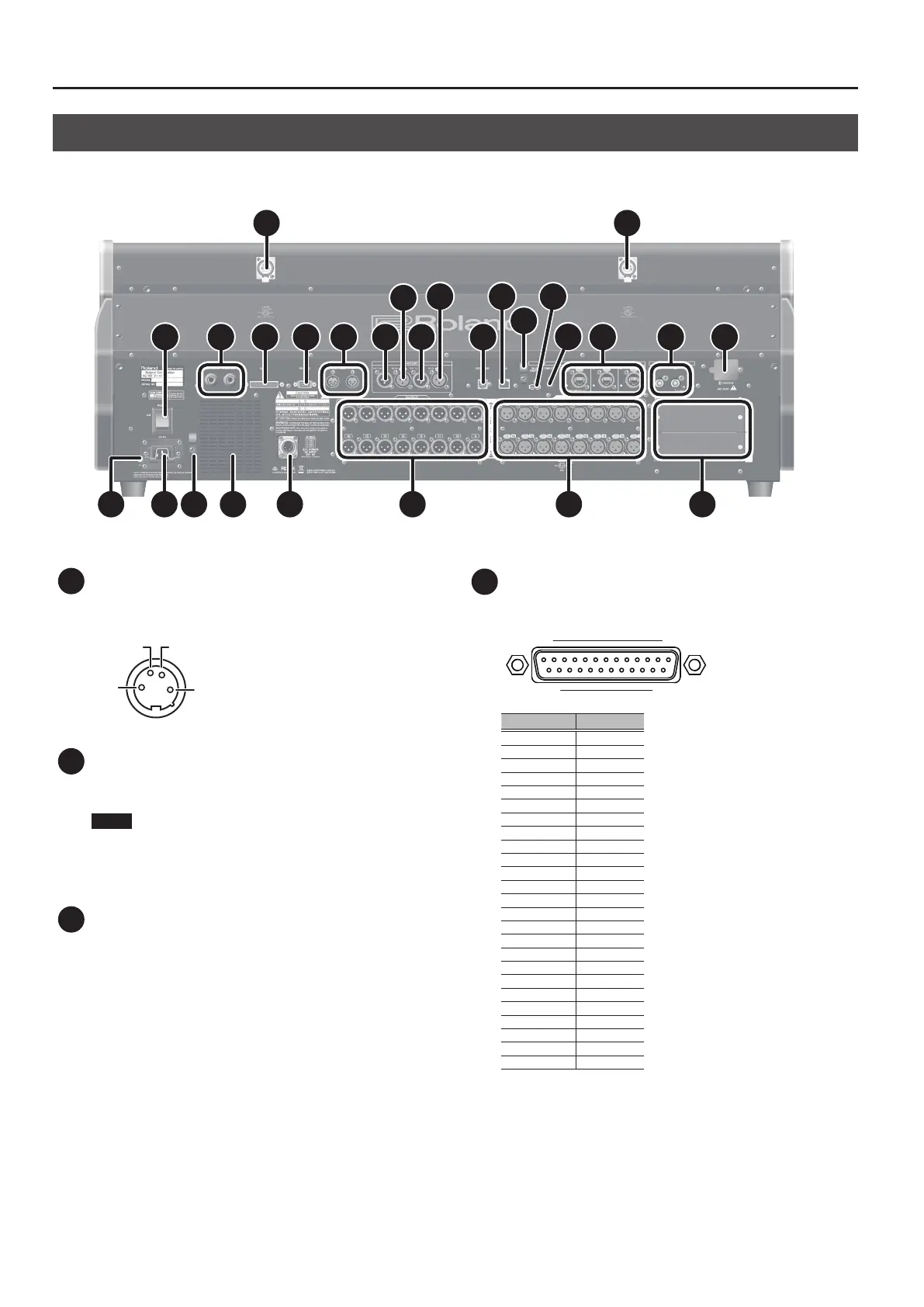
Rear Panel
1 1
2
10
13
3 4 5 6 7
8
7
8
9
12
14 15 16
18 17 19 20 21 22 23 24
11
1 LAMP Connectors
These are XLR-4-31 connectors that supply power to third-party
gooseneck lamps.
GNDNC
NC DC+12V [DC+12V/500mA]
1
2
3
4
2 POWER Switch
This turns the power on and o.
0“Turning the Power On and O” (p. 20)
NOTE
If you need to turn o the power completely, rst turn o the
unit, then unplug the power cord from the power outlet. Refer to
“To completely turn o power to the unit, pull out the plug
from the outlet” (p. 4).
3 FOOT SW 1/2 Jacks
These are TRS standard jacks for connecting footswitch pedals.
4 GP I/O Connector
This is a D-sub 25-pin connector (4 in/12 out) for sending and
receiving control signals to and from an external device.
113
1425
Connector No. Type
1 GPO 1
2 GPO 3
3 GPO 5
4 GPO 7
5 GND
6 GND
7 GND
8 GND
9 +5V
10 GPI 2
11 GPI 4
12 GPO 10
13 GPO 12
14 GPO 2
15 GPO 4
16 GPO 6
17 GPO 8
18 GND
19 GND
20 GND
21 +5V
22 GPI 1
23 GPI 3
24 GPO 9
25 GPO 11
Input pin [Voltage detection range: 0-5V , Max +5V]
Output pin [Open collector , Vmax=12V , Imax/pin=75 mA]
DC output [DC+5V / 1000mA]
 Loading...