Noms et fonctions des diérentes parties
37
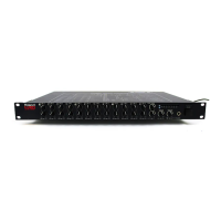
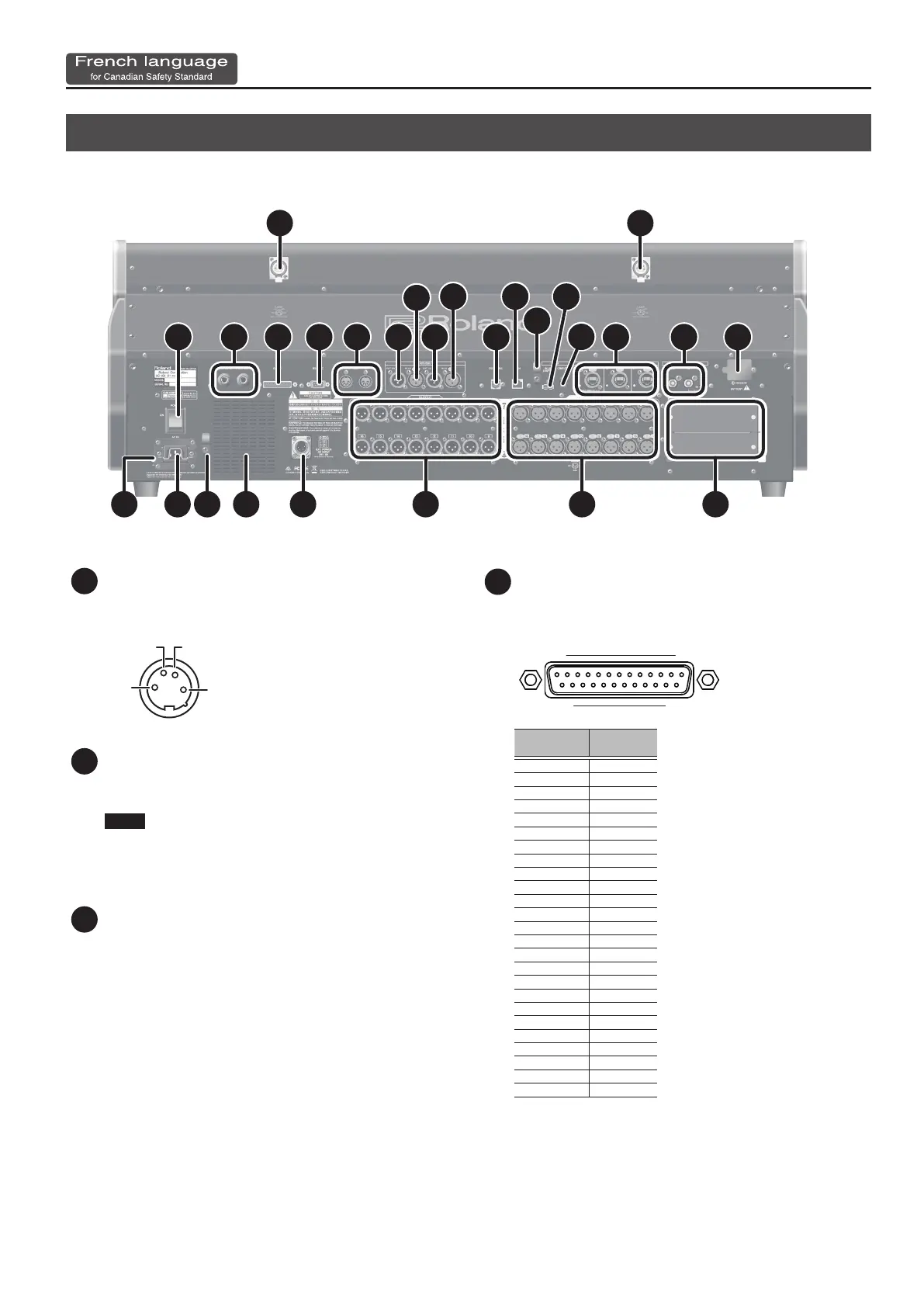
Panneau arrière
1 1
2
10
13
3 4 5 6 7
8
7
8
9
12
14 15 16
18 17 19 20 21 22 23 24
11
1 Connecteurs LAMP
Ce sont les connecteurs XLR-4-31 qui alimentent les lampes à col de
cygne tierces.
GNDNC
NC DC+12V [DC+12V/500mA]
1
2
3
4
2 Commutateur d’alimentation POWER
Permet de mettre sous ou hors tension.
0“Mise sous tension et hors tension de l’appareil” (p. 21)
NOTE
Si vous devez éteindre complètement l'alimentation, éteignez
d’abord l'appareil avant de débrancher le cordon d'alimentation
de la prise de courant. Consultez “Pour éteindre complètement
l’alimentation de l’appareil, retirer la che de la prise” (p. 6).
3 Prises FOOT SW 1/2
Ce sont des prises standard TRS pour connecter les commutateurs
au pied.
4 Connecteur GP I/O
Il s'agit d'un connecteur D-sub à 25 broches (4 in/12 out) pour
envoyer et recevoir des signaux de commande vers et depuis un
dispositif externe.
113
1425
Connecteur
No.
Type
1 GPO 1
2 GPO 3
3 GPO 5
4 GPO 7
5 GND
6 GND
7 GND
8 GND
9 +5V
10 GPI 2
11 GPI 4
12 GPO 10
13 GPO 12
14 GPO 2
15 GPO 4
16 GPO 6
17 GPO 8
18 GND
19 GND
20 GND
21 +5V
22 GPI 1
23 GPI 3
24 GPO 9
25 GPO 11
Broche d'entrée [Plage de détection de tension: 0-5V , Max +5V]
Broche de sortie [Collecteur ouvert, Vmax=12V , Imax/pin=75 mA]
DC sortie [DC+5V / 1000mA]
 Loading...