© 2017 Ropam Elektronik
Optical status indication.
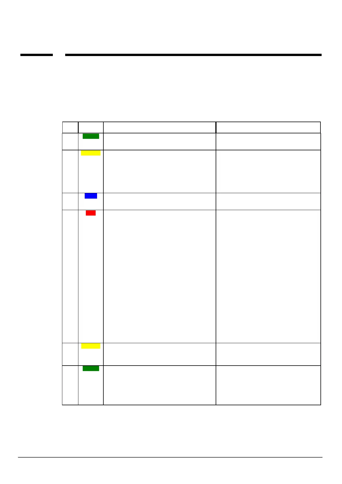
The device is equipped with state optical signaling. On the PCB there are LEDs that indicate the status
of work: notification, PC communication, firmware upgrade.
SIGNALING PROGRAMMING STATE
• short flashes every 8 seconds. = correct
communication with GSM modem
• blinking alternating (wave); COMM-SEND-LOG-
FAIL = change firmware in module (active
communication)
• sending SMS and voice notification, the notification
action is as follows:
NOTIFICATION OF SMS
-1 flash = send SMS on NUMBER 1, ... 8 flashes =
send SMS on NUMBER 8,
VOTE NOTIFICATION
- 1 flash = connection to NUMBER 1, ... 8 flashes =
connection to NUMBER 8,
• blinks every 1s. = connection to a service
computer
• blinking alternating (wave); COMM-SEND-LOG-
FAIL = change firmware in module (active
communication)
• series of short flashes from 1 to 5 every 2 seconds
= GSM network level status (1-min 5 = max)
• no flashing = phone not logged on GSM network
• blinking alternating (wave); COMM-SEND-LOG-
FAIL = change firmware in module (active
communication)
• a series of short flashes approx. every 2 seconds =
TROUBLE CODE (including SMS STATE):
01 - low level of network, below 2 "bars" (RSSI <15)
02 - modem not logged on GSM network
03 - failed to send three SMS messages in series (kept
for correct transmission)
04 - connection to the monitoring station
05 - GPRS problem (message transmission: EMAIL)
06 - no communication with GSM modem
07 - PIN code error (PUK lock)
08 - SIM card problem, SIM card not detected by
modem
09 - Jamming was detected
10 - overload or short circuit of AUX output
11 - power supply problem (too low or too high module
power supply - see table: technical parameters)
12 - battery error (uncharged, no voltage)
13 - configuration data corruption in EEPROM
(memory)
14 - power failure 1 wire
15 - Serial Flash failure
16 - RTC failure, wrong time setting
17 - no connection to RopamBridge
18 - outage blocked daily counters: sending SMS,
ringing, sending an email
• blinking alternating (wave); COMM-SEND-LOG-
FAIL = change firmware in module (active
communication)
• not lit = no incoming calls to module number
• lit = incoming call, receiving SMS to module number
• INCOM 1s / 1s blinking = connected to
RopamBridge
• lit = for versions - PS basic power supply current
17V / AC or 24V / DC
• blinks = for versions - PS no power supply, battery
power, for 12V DC power supply correct