© 2017 Ropam Elektronik
6. Connect the wires to the appropriate terminals, eg signaling devices, relays
7. Connect the external antenna to the SMA-F connector (in the system casing, move the SMA
connector from the SMA-F connector to the casing hole).
8. Turn on the module power.
9. Connect the cable connecting the service computer to the USB-Micro jack.
10. Configure the system as needed.
11. Make tests and tests.
12. Disconnect the cable from the USB-microphone connector.
Connection of devices to the inputs.
The system supports many types of input polarization.
Can work with any of the following:
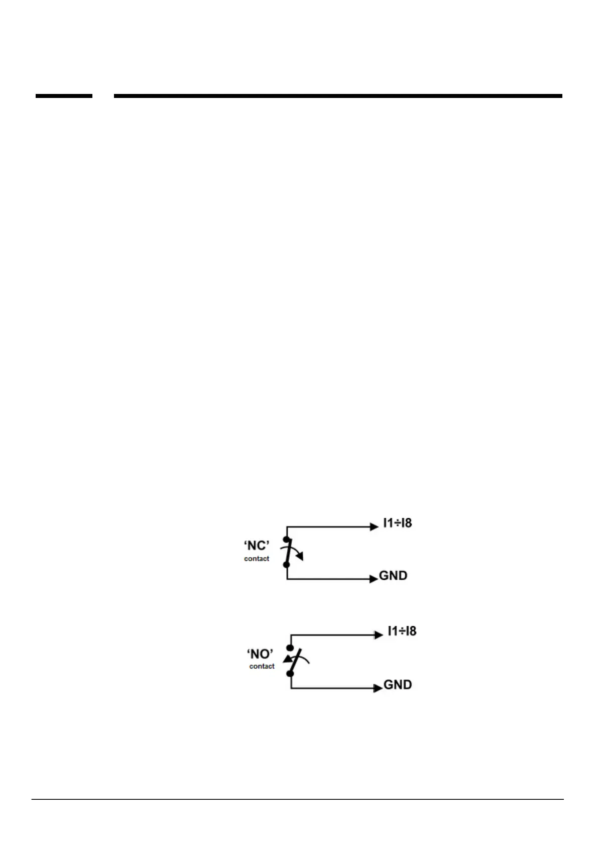
- Detectors for outputs: NC (Normally Closed), NO (Normally Open)
- alarm outputs: relays (RELAY - potential-free contacts),
- open collector (OC - BELL): control "negative" power,
- high current (transistor: control + 12V)
- Analog outputs 0-10 [V], 4-20 [mA] (I7 and I8 only)
Configuration input: NC.
Configuration input: NO.