12
Operating instructions G series UTD.187.2019.09.00_EN
UTD.187.2019.09.00_EN Operating instructions G series
* Recommended length.
1) Values not to standard.
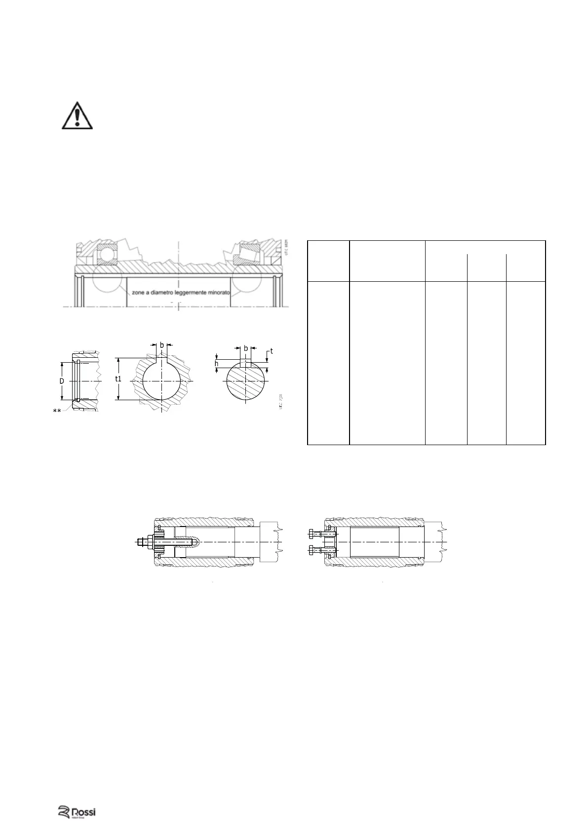
5.6 - Mounting of hollow low speed shaft
For machine shaft ends onto which the hollow shafts of gear reducers are to be keyed, h6, j6, and k6 tolerances
are recommended, according to requirements.
Important! the shoulder diameter of the driven machine shaft end abutting with the gear reducer must be at least
1,18 ÷ 1,25 time the hollow shaft internal diameter. For other data on machine shaft end (in case of standard
hollow low speed shaft, stepped shaft, with locking rings or bushings) see Rossi technical catalogs.
Attention! For vertical ceiling-type mounting and only for gear reducers equipped with locking rings
or bushing, gear reducer support is due only to friction, for this reason it is advisable to provide it with
a fastening system.
Attention! Even if the hollow low speed shafts machined in tollerance H7, a check through bott could reveal
two areras with a slightly underdimensioned diameter (see Fig. 1): this und underdimensioning is intentional
and not aff ecting the keying quality – which is improved in terms of duration and precision – and is not
hindering the assembly of machine shaft end according to usual methodes, such as the one shown at fi g. a).
Attention! In order to facilitate the mounting of gear reducer onto machine shaft end, diameter D (**, see
Fig. 2) is slightly overdimensioned as to nominal dimension, at hollow shaft input (standard, stepped, with
shrink disc): this will not aff ect realiability.
5.7 - Gear reducer installing and removing
In order to have an easier installing and removing of gear reducers and gearmotors with retaining ring groove
(sizes 64 ... 360) – both with keyway and shrink disc – proceed as shown at fi g. 5.7.1 and 5.7.2 (excluding MR
3I 100 with motor sizes 112 and 3I 125 with motor size 132; consult us).
For MR 3I 64 ... 81, fi rst insert the washer with screw and the retaining ring into the gear reducer hollow shaft
(on motor opposite side); then mount on machine shaft end.
Gear reducer Machine shaft
Fig. 5.6.1
Fig. 5.6.2
Fig. 5.7.1
Fig. 5.7.2
Hollow low speed shaft
Hole Parallel key Keyway
D
b
h
l*
b t
t
1
Ø H7
h9 h11 H9 hub
N9 shaft shaft hub
19
6 × 6 × 50 6 3,5 21,8
24
8 × 7 × 63 8 4 27,3
30
8 × 7 × 63 8
4,5
1)
32,7
1)
32
10 × 8 × 70 10 5 35,3
38
10 × 8 × 90 10
5,5
1)
40,7
1)
40
12 × 8 × 90 12
5
1)
43,3
48
14 × 9 × 110 14 5 51,8
60
18 × 11 × 140 18 7 64,4
70
20 × 12 × 180 20
8
1)
74,3
1)
80
22 × 14 × 200 22 9 85,4
90
25 × 14 × 200 25 9 95,4
100
28 × 16 × 250 28 10 106,4
110
28 × 16 × 250 28 10 116,4
125
32 × 18 × 320 32 11 132,4
140
36 × 20 × 320 36 12 148,4
160
40 × 22 × 400 40
14
1)
168,3
1)
180
45 × 25 × 400 45 15 190,4
 Loading...