39
11. Assembly(installation)
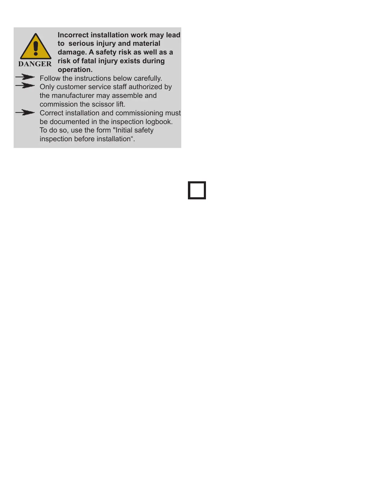
Incorrect installation work may lead
to serious injury and material
damage. A safety risk as well as a
risk of fatal injury exists during
operation.
Follow the instructions below carefully.
Only customer service staff authorized by
the manufacturer may assemble and
commission the scissor lift.
Correct installation and commissioning must
be documented in the inspection logbook.
To do so, use the form "Initial safety
inspection before installation“.
11.1 Assembly safety instructions
• Verify that the foundation is suitable before as-
sembling.(→ Chapter 7 Technical data.)
• Think about and prevent potential sources
of danger before assembly (→ Chapter 1.
Intended use, improper use, incorrect behavior,
and internal incident, health & safety, and
environmental information).
• Operators must be able to view the scissor lift
and the danger zone in full from the control unit
(→ Chapter 3.2. Work area, danger zone).
• Refer to the technical data in chapter 7.
• Route and protect on-site power cables according
to manufacturers specications.
• Only qualied electricians may carry out electrical
work on the electrical equipment of the machine.
• Only qualied staff with specialist knowledge and
experience with hydraulics or pneumatics may
work on hydraulic or pneumatic equipment.
• When working on the hydraulics or on pneumatic
equipment, ensure that you follow the safety
regulations listed in the supplied power unit oper-
ating instructions annexed to this manual.
• Ensure that you also follow the instructions
listed in 2. Safety.
11.2 Site specications
•
The scissor lift may only be installed above
ground and indoors.
•
Refer to the building plans when selecting a site.
•
When anchoring to the oor, take into account
any pipes, cables, and supply lines lying there.
•
Ensure that the load capacity of the foundation is
adequate.
•
Support surface for lift base frame:
Reinforced concrete, concrete quality C20/C25
•
Floor must be designed for a oor anchor.
•
Concrete dimension .(→ Chapter 7 Technical
data.)
•
Check the height of the area where the lift is to
be installed. Clearance should be calculated
based on the full raised height of the lift and the
height of the tallest vehicle being lifted.
Do not t scissor lift onto asphalt or a
similar unstable surface, since the anchor
may come loose in the oor.
•
Comply with the specied minimum distances
and clearances ( → Chapter 3.2. Work place,
danger zone)
11.3 Installation preparations
1. Provide an electrical outlet close to the lift control
cabinet:
•
Electrical, according to the lift variant :
3 ph (3xL+PE) for power supply
1ph (L+N+PE) for power supply
see electric wiring diagram in annex.
2. Level out any uneven oor areas around the
lift columns. If required, ll bearing surfaces for
lift columns with reinforced concrete (concrete
quality C20/C25).
3. Equalize slight differences in height between lift
base frame using spacers or shims.
 Loading...