40
11.4 General lift location
1.Use architects plan when available to locate lift.
see Chapter 7 Technical data.
2.Control cabinet may be placed on the left or right.
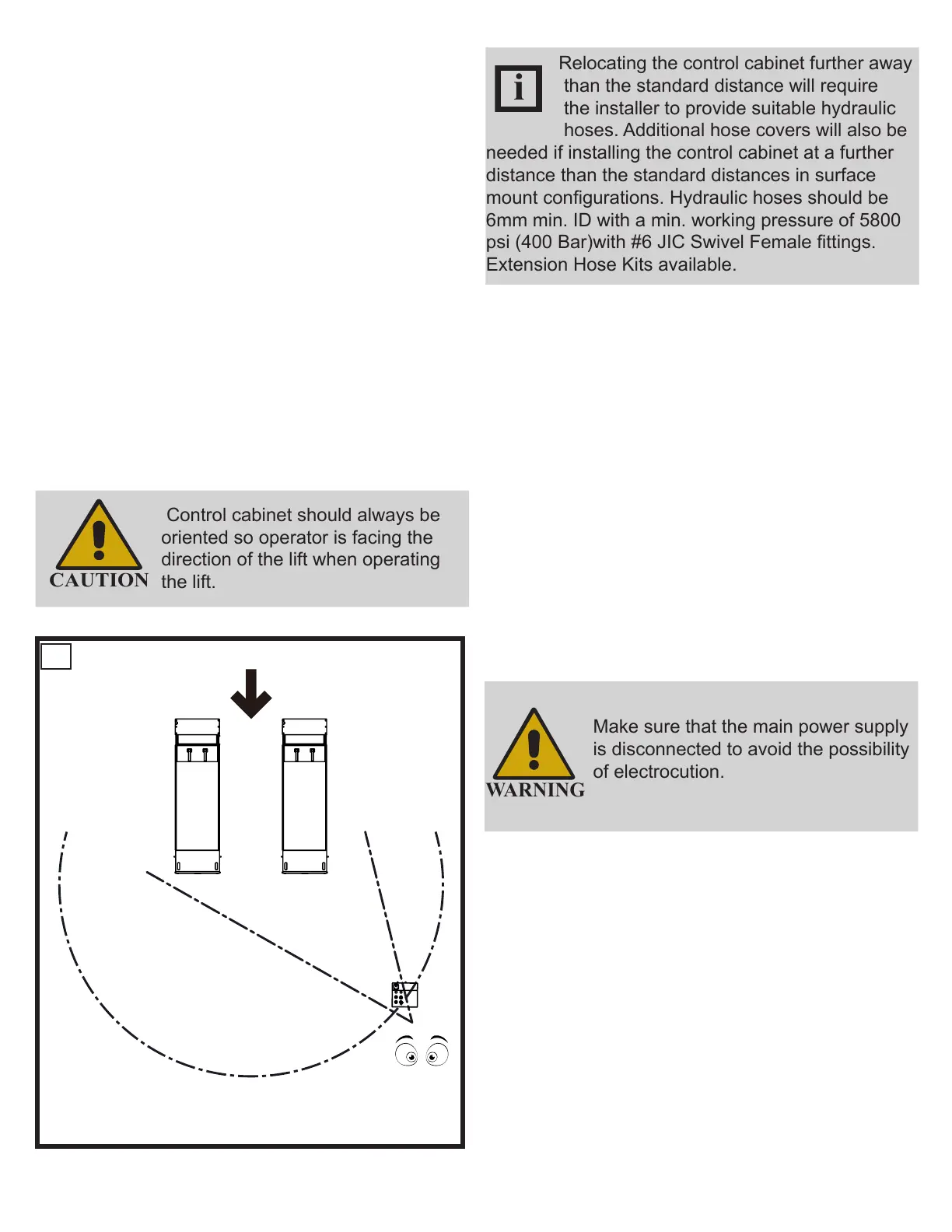
3.Place platforms and control cabinet as shown
in Fig. 17 for surface mount or ush mount
applications.
DO NOT anchor any components at this time.
The control cabinet should be located on the
opposite end of vehicle approach, as shown in
Fig. 17. Operator should be in a position to notice
any misalignment of lifting pads or vehicle during
operation. Rotary Lift does not recommend placing
the control cabinet in a different location orientation
and doing so would be the responsibility of the
installer and/or end user.
Recommended Direction of Approach
Control cabinet should always be
oriented so operator is facing the
direction of the lift when operating
the lift.
17
Relocating the control cabinet further away
than the standard distance will require
the installer to provide suitable hydraulic
hoses. Additional hose covers will also be
needed if installing the control cabinet at a further
distance than the standard distances in surface
mount congurations. Hydraulic hoses should be
6mm min. ID with a min. working pressure of 5800
psi (400 Bar)with #6 JIC Swivel Female ttings.
Extension Hose Kits available.
11.5 Control Cabinet Connections
•
Electrical Connection:
Have a certied electrician run appropriate power
supply to motor wire size for a three phase 400V
with 16 amp \ three phase 220V with 25 amp or
single phase 32 amp. circuit.
•
Never operate the motor on line voltage less than
208V. Motor damage may occur.
All wiring must conform to all national and local
electrical codes.
Make sure that the main power supply
is disconnected to avoid the possibility
of electrocution.
•
Connect the limit switch wires to PCB on control
cabinet ,g 18.
•
.Verify the power connection on the control
cabinet connections are complete and correct
base on the wiring schematic(see annex) and
motor connection .g19.
• Connect to power supply line.
DS35EX
 Loading...