d06703.fm
03 July 2019 76-10-00
Initial Issue Page 6 of 18
Copyright - BRP-Rotax GmbH & Co KG. All rights reserved.
SI-912 i-024
SI-915 i-006
SERVICE INSTRUCTION
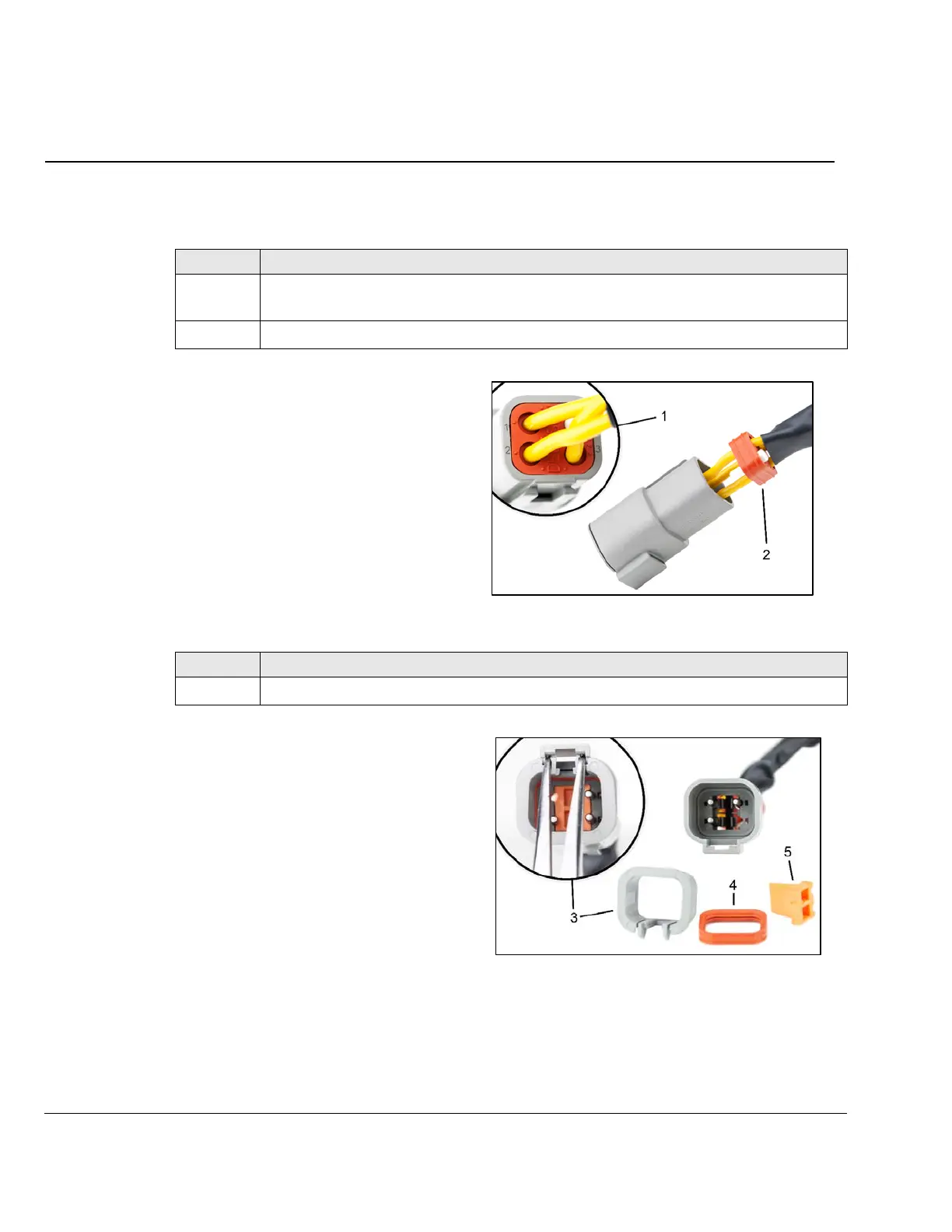
3.3.1) Replacement of male connector (regulator side)
In order to preserve maximum wire length, remove the wires with crimped male pins from regula-
tor B connector housing (gray).
Fig. 1
Fig. 2
Step Procedure
1
Label each of the 3 yellow wires with its location within the connector. The rear of the
connector housing (1) is marked with numbers.
2 Gently pry the rectangular rubber seal (2) from the rear of the connector.
Step Procedure
3 Using fine-nosed pliers, pull the retaining wedge (5) from the connector housing.
1 Connector housing
2 Rubber seal
3 Retaining sleeve
4 Sealing ring
5 Retaining wedge

 Loading...


