d06703.fm
SI-912 i-024
SI-915 i-006
SERVICE INSTRUCTION
03 July 2019 76-10-00
Initial Issue Page 7 of 18
Copyright - BRP-Rotax GmbH & Co KG. All rights reserved.
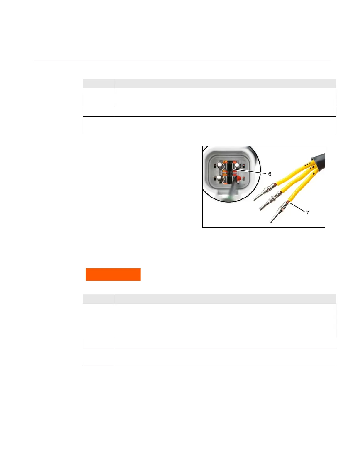
Fig. 3
Attach Amphenol® male connector to regulator B
The following instructions depict the use of DMC® adjustable crimp tools. These tools or equiva-
lent are required to correctly attach connecting pins.
Step Procedure
4
Remove pins from connector housing by releasing plastic retaining tabs (6) and pull-
ing wires from behind.
5 Cut off each wire at crimped pins (7) with a standard cutter.
6
Ensure that wires are still clearly numbered and pull rectangular rubber seal from the
wires.
Failure to use correct crimping tool(s) may lead to engine damage, person-
al injury or death.
Step Procedure
1
Carefully strip off approximately 10 mm (0.39 in.) of insulation from each of the three
yellow wires.
NOTE: Use a quality wire-stripping tool set to 12 AWG (3.31 mm
2
) to avoid dam-
aging wire strands.
2 Set the crimp tool’s wire size to 12 AWG (3.31 mm
2
) (8).
3
Stripped wires must seat fully into crimp pin and have approximately 1 mm (0.039 in.)
insulation gap (9).
6 Retaining tabs
7 Cut off pins

 Loading...


