35
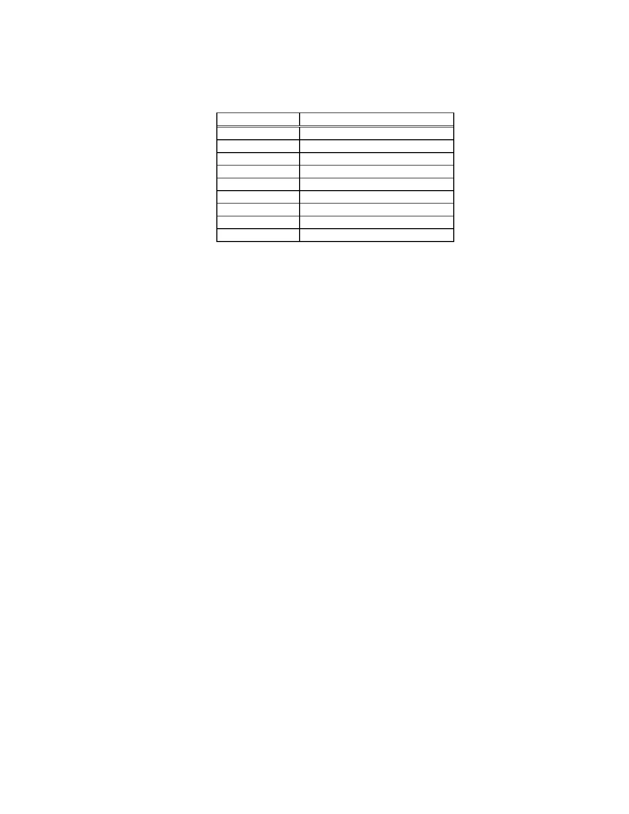
Operation of the relays should be checked to the following table.
Relay Signal for Operation
K1 1.0100 - 50.000 Amps
K2 1.0100 - 50.000 Amps
K3 100.00mA - 1.01 Amps
K4 10.000mA - 100 Amps
K5 10.000 - 50.000 Amps
K6, K6A Operate
K7 100 - 749V
K8 Operate
K9 100 - 749V
If a relay is not functioning, trace through the digital logic on the Control Logic module, 08-
113-001. For example if K3 is not operating: IC42-10 should be high, IC10-14 low; If not, examine or
replace. Suspect defective IC.
4.5.3 Suspected Voltage Failure
Refer to Figure 4-8, 08-800-002/1.
1. DC Offset. (08-115-001 3/3)
Turn line power on, line Synchronization off; do not enter voltage or wattage data. Measure the
DC voltage at TP9 of the CVA 08-115-001; it should be 0 ±1mVDC. If it is not, adjust R196 on
the CVA per Paragraph 4.1 of Table 4-3; if it cannot be adjusted one of the following components
is failed.
AR6 or AR10
IC8 through IC11
Q2-Q4
Q11, 12, 26, 27
2. Quiescent Current
Measure the DC voltages across R25 and R25A on the rear panel assembly (08-103-000). They
should be 100mVDC. If not adjust R124 on the CVA Module. If it cannot be adjusted and reads
low, possibly there is an open output stage Q11, Q12, Q26, Q27 on the rear panel assembly. If it
reads high check for open diode CR7 through CR11, R124 open or defective Q2, Q3, Q4 on the
CVA or shorted Q11, Q12, Q26, Q27 on rear panel.
3. Reference Voltage.
Turn line power off. Remove fuses F1 through F4 on rear panel assembly. Turn line power on,
enter 10.0 volts and press Operate. This configuration can be used to obtain a low (10V) output
without danger of large output stage currents. Measure the voltage at TP2 on the Reference 08-
121-001, it should read approximately -7 volts. If not, RX1, CR1, AR1 or Q1 is defective.
Measure the voltage at TP3 on the Reference Module, it should read +10.000VDC, if not AR2 or
Q2 is defective.