Connection of the gas supply pipe —
checking the gas type and burner
settings
Warning: Risk of explosion
Incorrect handling of gas
equipment can lead to gas
explosions: Danger to life Only authorised
gas fitters are allowed to work on gas
equipment.
The gas connection must meet the technical
rules for gas installations in accordance with
current regulations of the gas supply company
and the relevant country of installation. At the
equipment, the gas supply pipe is connected to
the type-tested corrugated gas hose (pipe
thread DIN 2999 - Rp 1/2“) (Fig. 3.4.5).
static gas inlet pressure (Fig. 3.4.6) and
compare it with the values listed in Tab. 3.4.1.
The standard gas supply hose can cause a
pressure drop of approx. 5 mbar. The supply
pressure at the gas valve can therefore be
below the value in the table by that amount.
This will not have a negative influence on the
equipment function.
1)
Notify your gas supply company if the gas
supply pressure falls outside the stated range.
2)
Where the rated pressures deviate, observe
the limits in accordance with the regulations
of the relevant country.
Tab. 3.4.1: Gas supply pressure
The connection hose is factory-fitted, so that
the burner can be removed for maintenance
work, without needing to be disconnected
from the gas mains.
Install a thermally activated shut-off valve
(TAE) and a gas flow limiter (GSW) with DVGW
test symbol [check local regulations] on site.
The TAE must comply with the test standard
according to DVGW-VP 301 [or local regula-
tions]. Size the GSW in accordance with the
maximum selectable rated load of the equip-
ment.
The gas type must be identical to that stated
on the yellow label on the burner fan. If the
burner is not identified as being suitable for
the available gas type, convert the burner to
the available gas type and mark it accordingly
(see chapter 5.1). Test the
[ 19 ]
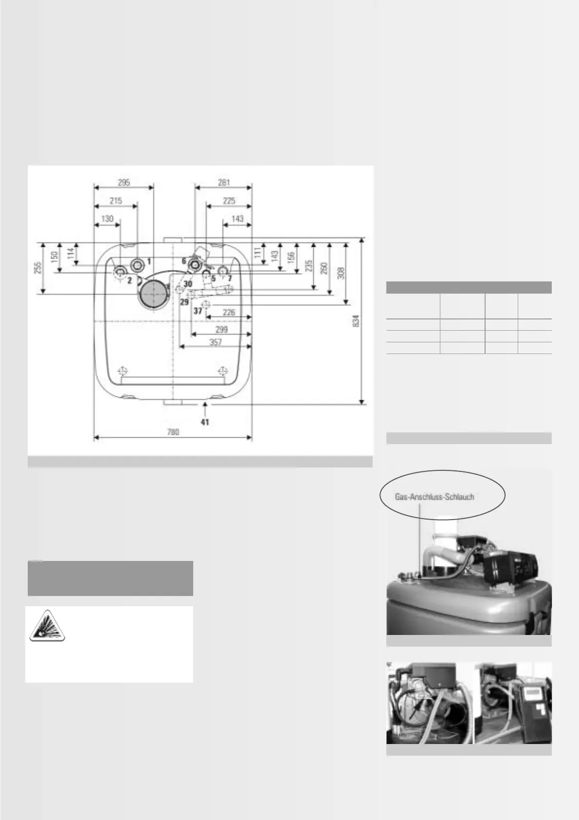
Fig. 3.4.4: Connection dimensions for the heating and DHW connection (top view)
Fig. 3.4.5: Gas connection
1 Cold water (pipe thread 1“ male)
2 DHW (pipe thread 1“ male)
5 Heating flow (pipe thread 1“ female)
6 Heating return (pipe thread 1“ female)
30 Diaphragm
expansion vessel (pipe thread
3
/4
“ male)
7 Solaris flow (pipe thread flat
packing 1“ union nut)
29 Safety blow- (pipe thread
3
/4
“
off line female)
37 Boiler fill &
drain valve (pipe thread
1
/2
“ male)
Gas type Inlet pressure in mbar
1)
Rated min max.
pressure
Natural gas E, H 20 17.0 25.0
Natural gas LL 20 17.0 25.0
LPG
2)
50 42.5 57.5
Fig. 3.4.6: Checking gas inlet pressure
back
front