When the maximum cylinder temperature has
been reached, the three-way diverter valve
will be switched over to “Heating” (Fig. 3.5.1:
connection B; the manual lever (pos. 5.3)
points away from the valve body).
Note: Special screed functions are
available to heat up an underfloor
heating system (see “Operating
instructions for contractors - ROTEX
control unit”).
Fig. 4.2.1: Manual mode
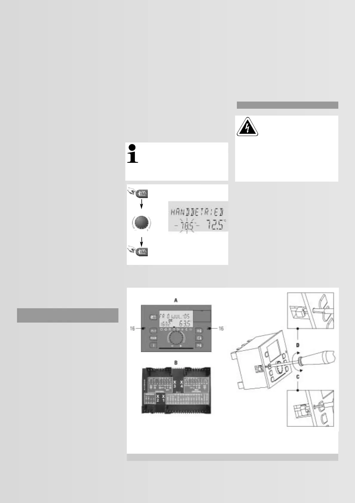
4.3 Replacing the control unit
Warning:
Electric shocks can cause severe burns
and life-threatening injuries. Before
commencing any maintenance work,
isolate the heating system from the power
supply by switching the mains isolator
OFF, and safeguard against unintentional
reconnection (pull the power supply plug
from the plug-in PCB).
Both fixing screws (pos. 16 in Fig. 4.1.1) of the
electronic control unit can be undone by
turning them anti-clockwise. This can then be
pulled out towards the front (Fig. 4.3.1 and
4.3.2).
Fig. 4.3.1 also shows the back of the ROTEX
THETA 23R control unit. When the control unit
is reinserted into the control panel, the
connection pins will be pushed firmly onto the
permanently fixed socket on the PCB. Then
tighten the fixing screws again by turning
them clockwise.
15 Abridged operating instructions
16 Control unit fixing screws
17 Level monitoring indicator for ade-
quate water level
This indicator shows that the cylinder is
sufficiently full of water.
It is switched ON when all three elec-
trodes of the level probe (pos. 42 in Fig.
2.1.1, Fig. 2.1.2 and Fig. 2.2.1) are
immersed in water and illuminates, as
long as at least two electrodes are
immersed in water.
A burner demand will only be enabled if
the level is adequate.
18 Level warning indicator for low water level
This indicator shows that the cylinder is insuf-
ficiently full of water. It is switched ON when
not at least two of the three electrodes of the
level probe (pos. 42 in Fig. 2.1.1, Fig. 2.1.2 and
Fig. 2.2.1) are immersed in. The unpressurised
sector of the cylinder needs to be full of water
to safeguard a reliable DHW provision and to
enable the Solaris to operate effectively.
Any burner demand will be blocked if the level
is too low.
4.2 Manually adjusting the boiler water
temperature
In standard operation, the boiler water control
thermostat will either be set to automatic or
constant operating mode. The boiler water
temperature will be regulated subject to
weather conditions. The control unit can be set
the “Manual mode” by holding down the man-
ual key for approx. 5 s (pos. 13 in Fig. 4.1.1),
for a manual heating up of the heating system
or to temporarily select the boiler water tem-
perature manually. The required temperature is
adjusted via the rotary selector (pos. 6 in Fig.
4.1.1).
Setting range: 5-80 °C.
In manual mode (Fig. 4.2.1), the three-way
diverter valve (pos. 25 in Fig. 2.2.1) will initially
be in the “Cylinder heating” position (Fig.
3.5.1: connection A; the manual lever (pos. 5.2)
will point towards the valve body).
[ 28 ]
press for approx. 5 seconds
Set temperature
change
Return to the original operating
mode, standard display, the
selected set value is saved
Actual valueRequired set
value (flashing)
16 Clamping screws
A Front view
B Back view
C Turning anti-clockwise –
undoing the clamping screws
D Turning clockwise – tightening the
clamping screws
Fig. 4.3.1: Installing/removing the THETA 23R central control unit
 Loading...


