[ 15 ]
3.3 Positioning
Caution: Insufficient load
bearing capacity of the floor
can lead to damage to the
floor structure, the equipment and to risks
to individuals. Ensure that the floor has
a minimum load bearing capacity of
1050 kg/m
2
plus an appropriate safety
margin.
Caution: Risk of tipping
The GasSolarUnit is top-heavy
in its delivered condition. A
falling unit can easily be damaged and
injure an individual. Move the equipment
carefully with a hand truck or carry it at its
handles, whilst stabilising its position.
Secure the equipment particularly when
moving the equipment up or down stairs.
After removing the packaging, the ROTEX
GasSolarUnit/GasCompactUnit can be
installed at the intended site. The surface
where the system is to be installed must be
solid, level and horizontal. Where necessary,
install a suitable plinth. Route all connecting
cables/leads so that the silencer hood (Fig.
2.2.1, pos. 34) can be removed).
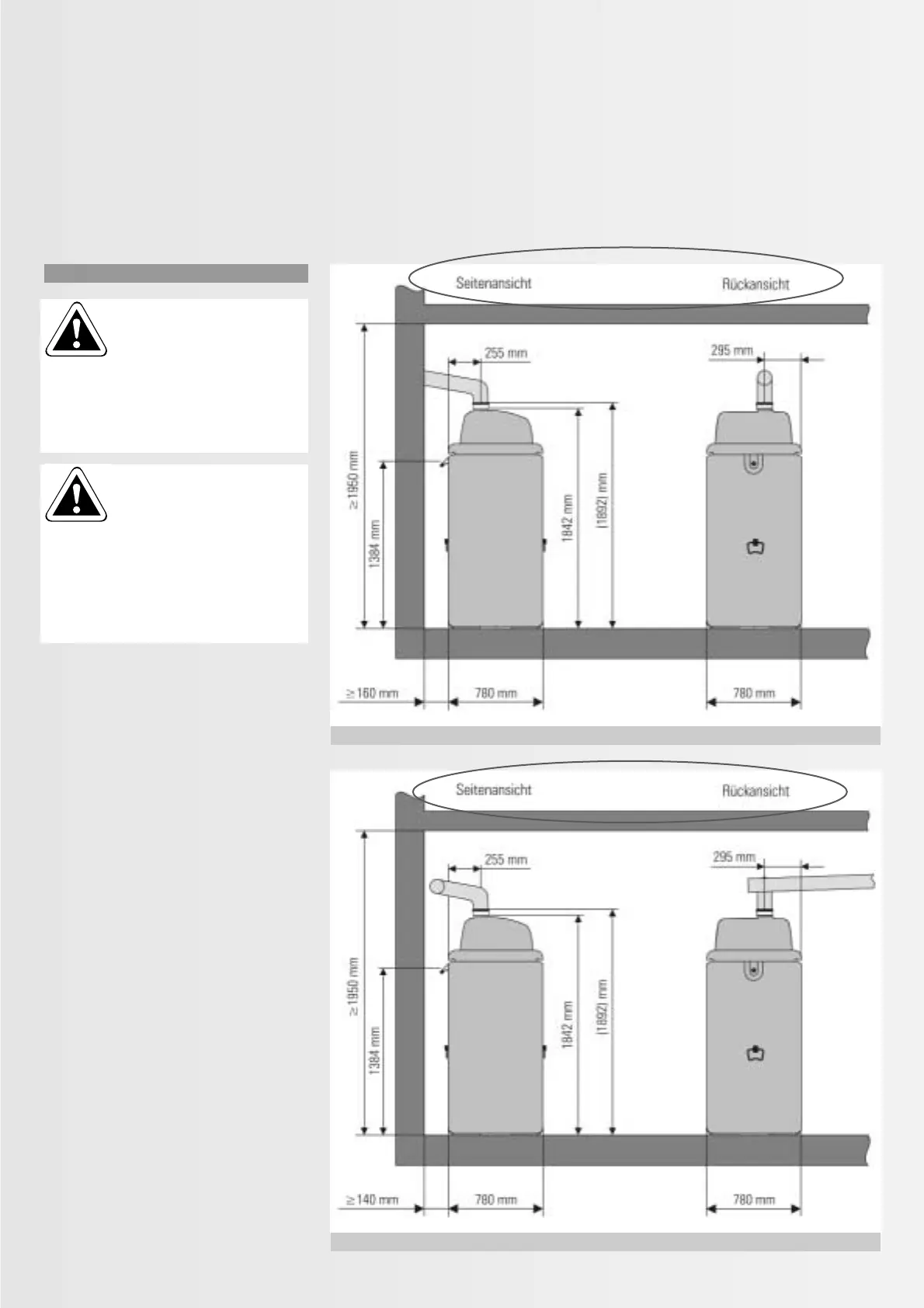
The GSU/GCU flue can be connected in three
different ways.
Standard connection is the direct flue
connection out the back (Fig. 3.3.1 - set H:
PPD-H, part no. 15 50 79.08).
If there is a chimney adjacent to the GSU/
GCU, then the side flue outlet can be used
(Fig. 3.3.2 - set K: PPD-K, part no. 15 50 79.09).
A flue connection with direct roof outlet is also
possible (set L: PPD-L, part no. 15 50 79.10).
For further details and connection dimensions
for the three flue connection options, see
chapter 3.4 section “Connection of the flue
and ventilation air line”.
Fig. 3.3.1 and 3.3.2 show the installation and
distance dimensions.
Fig. 3.3.1: Installation dimensions for flue connection out the back
Fig. 3.3.2: Installation dimensions for flue connection at the side
 Loading...


