[ 26 ]
Chapter 4: Boiler user interface
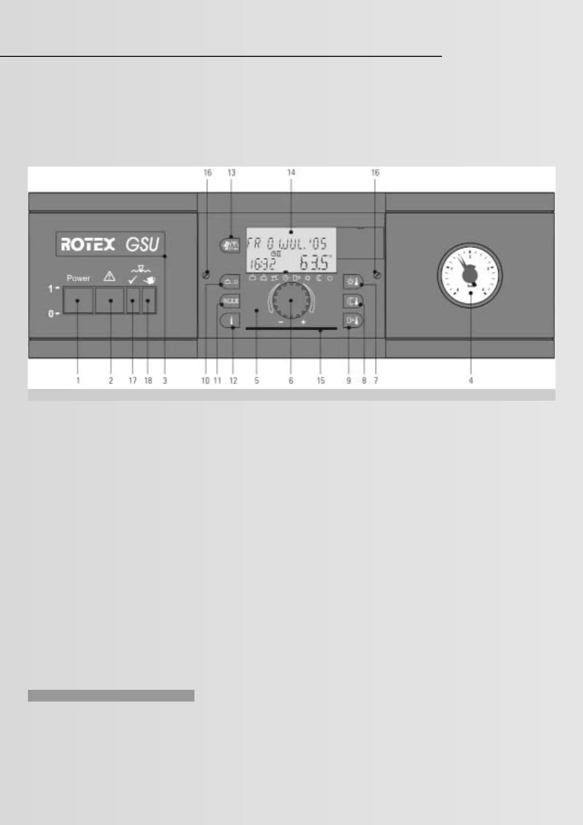
1 ON/OFF switch
2 Central fault message indicator
3 Legend to identify the equipment type
4 Pressure gauge
5 Control unit: Central control unit
THETA 23R
6 Rotary selector for selection
and adjustment
7 Key for the set day room temperature
8 Key for the setback room temperature
9 Key for the set DHW cylinder temperature
10 Operating mode selector
11 Key for the setting of the automatic
time program
12 Info key for system information
13 Key for emissions test and manual mode
14 Display (illuminated)
15 Compartment for the abridged
operating instructions
16 Control unit fixing screws
17 Level monitoring indicator
for adequate water level
18 Level warning indicator for low water level
4.1 Brief description
All important controls and electrical boiler
connections are integrated into the boiler
control panel. The electronics ensure the
trouble-free system operation. All display and
control elements are identified with position
numbers in Fig. 4.1.1; their description is given
in the following.
1 ON/OFF switch
Operate the ON/OFF switch to start/stop the
boiler. The ON/OFF switch illuminates green
when the heating system is switched ON. If
the heating system operates correctly, the
green level indicator (17) will also illuminate.
All other indicators will then be OFF.
2 Central fault message indicator
The illuminator will be OFF in standard
operation. There will be a fault if it illuminates
(e.g. unsuccessful starting attempt, sensor
break and similar).
Characteristics in case of a fault: The user can
restart the burner after a burner fault by
pressing the rest button (pos. 13) and display
“<< RESET” (pos. 14). Remove the cause if the
burner fault occurs repeatedly (see also
chapter 5.1 “Gas burner”).
Faults are generally displayed with fault code.
For troubleshooting information, see chapter 7.
3 Legend to identify the equipment type
This type immediately indicates, whether the
boiler is a GasSolarUnit or a GasCompactUnit
version. Except for this legend, the boiler
control panel for the GSU and the GCU are
identical.
4 Pressure gauge
This indicates the water pressure in the
heating system. During the system operation,
regularly check the water pressure at the
pressure gauge (pos. 4). The black needle
should be inside the green range and to the
right of the red indicator (see also chapter 3.5).
Top up with water if the system pressure drops
below the minimum pressure indicated by the
red needle. Check the on-site installation if the
pressure drops constantly.
5 Central control unit THETA 23R
The electronic digital control unit ROTEX
THETA 23R can regulate 2 heating circuits
(direct heating circuit and mixer circuit) as well
as one cylinder primary circuit. It comprises a
digital time switch with three individually
adjustable heating programs per heating cir-
cuit. As option, a DHW circulation pump can
be regulated. In addition, this control unit
enables up to 5 GSU/GCU or a heating circuit
extension with a heating circuit extension
module HEM 1 with up to four pieces of
equipment to be cascaded. Furthermore, a
modem can be connected for changing the
operation mode via telephone, and a burner
blocking contact (e.g. through a wood fired
boiler or a solar heating system) can be
hooked up.
Fig. 4.1.1: Boiler control panel