[ 32 ]
4.6 Replacing the fuse
Warning: Electric shocks can
cause severe burns and life-
threatening injuries. Before
commencing any maintenance work,
isolate the heating system from the power
supply by switching the mains isolator
OFF, and safeguard against unintentional
reconnection (pull the power supply plug
from the plug-in PCB).
Should the green ON/OFF indicator (pos. 1 in
Fig. 4.1.1) not illuminate, although the ON/OFF
switch is ON, and the display stays dark,
although the electrical supply to the boiler is
‘live’ and the mains isolator to the heating
system is switched ON, then most likely the
fuse has blown.
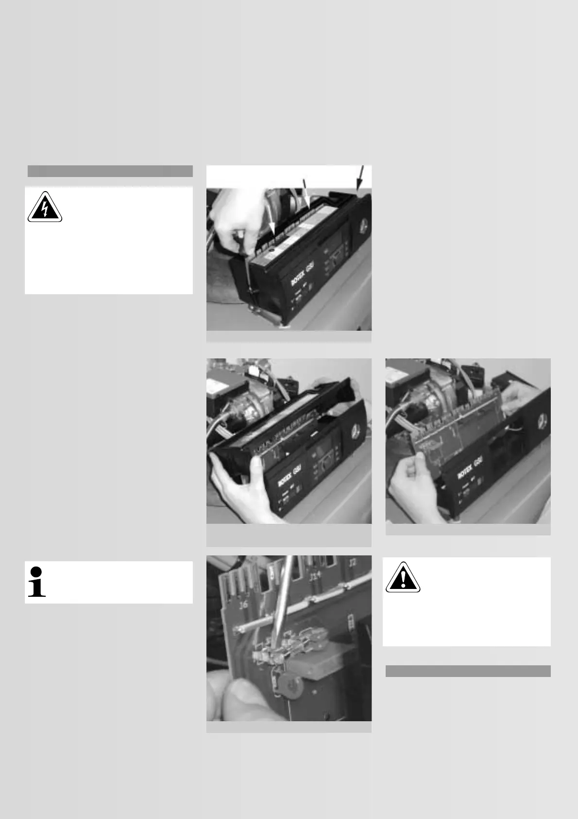
The fuse is located on the control panel PCB.
Initially, pull all plugs from the PCB (see Fig.
4.4.3 — proceed according to chapter 4.5,
steps 1 to 4). Now remove the 4 screws from
the control unit enclosure with a screwdriver
(Fig. 4.6.1) and remove the upper part of the
enclosure (Fig. 4.6.2). Now you can replace the
fuse as shown in Fig. 4.6.3. There is a short
circuit in the system, if the new fuse blows
again immediately after switching ON. That
must first be remedied by a qualified
electrician.
Fuse type:
Only use fuses type 250 V; 6.3 A (slow).
Note: A spare fuse is clipped into
the upper part of the enclosure.
4.7 Replacing the PCB
It is possible that the PCB has developed a
fault, if there is a fault that cannot be removed
neither by replacing the ROTEX THETA 23R
control unit (chapter 4.3) nor by replacing the
sensors and cables/leads in the control panel
(chapter 4.5). After pulling off all plugs from
the PCB (see Fig. 4.4.3 – proceed as per
chapter 4.5, steps 1 to 4), the removal of the
four screws from the control panel (Fig. 4.6.1)
and removing the upper part of the enclosure
(Fig. 4.6.2), you can pull the PCB upwards out
of the control panel and replace it (Fig. 4.7.1).
Important: Ensure that the
PCB plug inside the control
panel (fault indicator, main
ON/OFF switch) are replace on the new
PCB in the correct way (see Fig. 4.8.1). The
PCB must always be free from
contamination and scratches.
4.8 Component layout — wiring diagram
All important display elements and electrical
connections are integrated into the boiler
control panel. For the layout of the individual
components and the wiring diagram, see
Fig. 4.8.1.
Fig. 4.6.1: Removing the screws
Fig. 4.6.2: Removing the upper part
of the enclosure
Fig. 4.6.3: Replacing the fuse
Fig. 4.7.1: Removing the control panel PCB
 Loading...


