[ 45 ]
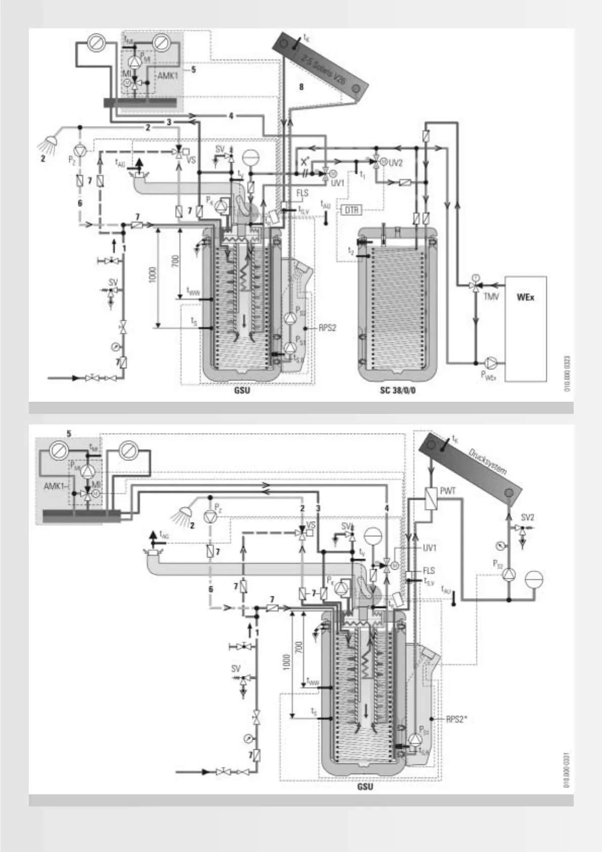
Fig. 5.3.4: optional connection of a pressurised solar heating system to the GasSolarUnit
1)
Fig. 5.3.3: Connection of a wood fired boiler to the GSU/ GCU
1)
1)
The connection diagram shown makes no claim as to its completeness and is no replacement for careful system engineering.
* Convert the Solaris control and
pump unit RPS 2: Remove the P
S2
.
The P
S2
can be used as solar circuit
pump. It is connected electrically
in parallel to the P
S1
.
* Separating the standard
connection: Remove UV1 and
reconnect it outside the
equipment.