47
FA ROTEX GW - 09/2012
12 x Technical data
Gas type, connection pressures
Integrated connection group (GW - all types)
Tab. 12-5 Technical data of the integrated connection group
Country of
destination
Appliance category Nominal connection
pressure in mbar
Natural
gas
Liquefied
petroleum gas
DE II
2ELL3B/P
20 50
AT, CH II
2H3B/P
20 50
GB, GR, IE, IT,
CH, ES, PT
II
2H3+
20 28-30/37
FR II
2Er3+
20/25 28-30/37
Tab. 12-3 Countries of destination, unit categories and associated gas
connection pressures (7)*
* Position numbers see fig. 12-1
Gas type Rated
pressure
in mbar
Min. inlet
pressure in
mbar
Max. inlet
pressure in
mbar
Natural gas E,H 20 18 25
Natural gas
L/LL
2)
20 18 25
Liquid petroleum
gas B/P
1)
28-30 / 37 25 35 / 45
1) When changing over to liquid petroleum gas, the subsequent burn-
er adjustment must be adapted to the permissible gas input pres-
sure. This adaptation must be made clear by an entry on the type
identification plate (fig. 4-17, item 27) and on the setting type iden-
tification plate (fig. 4-17, item 28).
2) When changing over to natural gas LL/L, this adaptation must be
made clear by an entry on the setting type identification plate
(fig. 4-17, item 28).
Tab. 12-4 Permitted gas inlet pressure
Heating circulation pump
Type Grundfos UPS0 15-60 CES
Voltage 230 V, 50 Hz
Maximum power consumption 78 W
Protection type IP 42
Permitted overpressure 3 bar
Maximum pumping height 5.8 m
Basic setting circulation pump Stage "3"
3-way diverter valve
Voltage 230 V, 50 Hz
Maximum power consumption 3 W
Protection type IP 44
Turnaround time 4 – 6 s
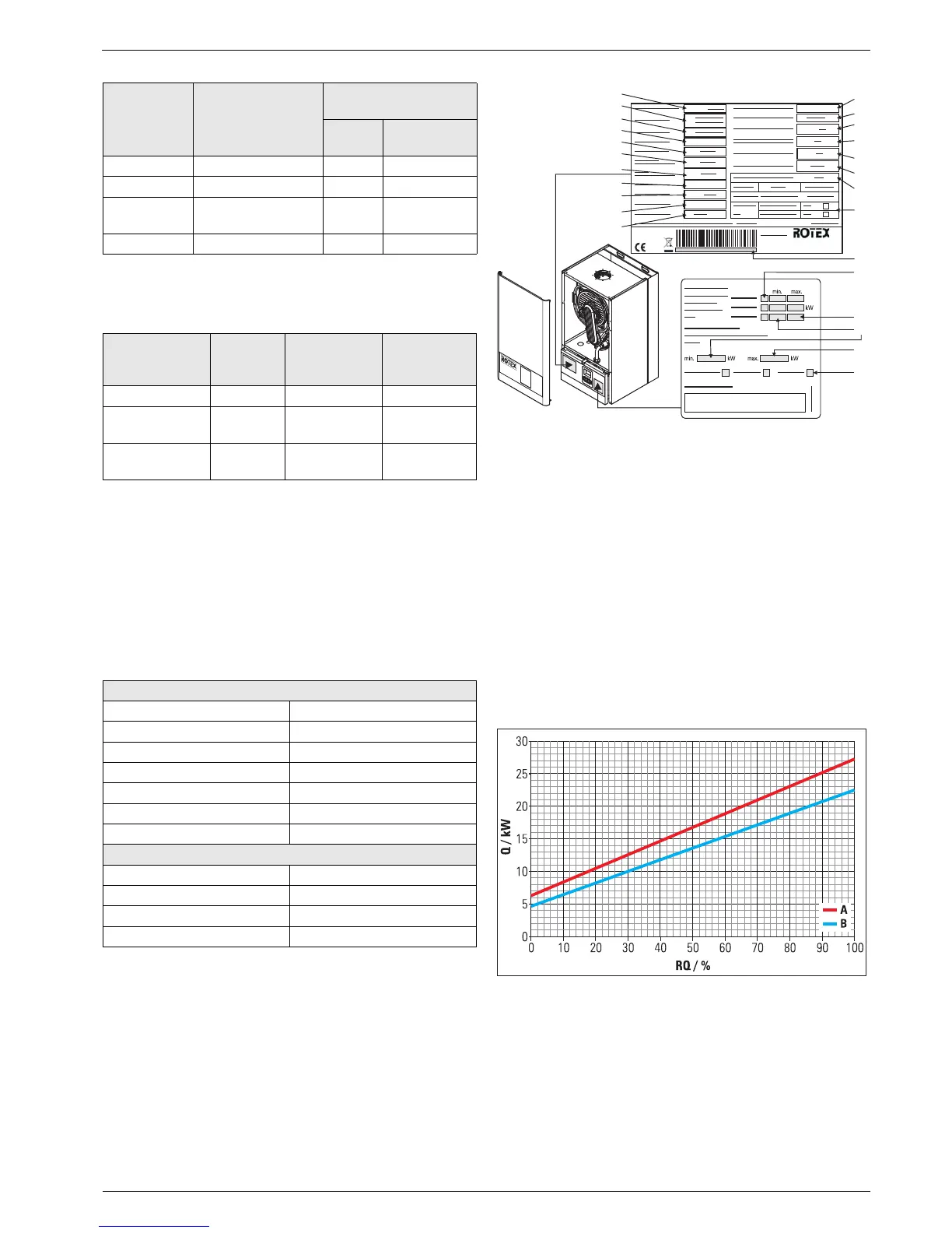
1 Type
2 Unit type
3 Product-ID (CE-Number)
4 NOx-class
5 Rated thermal load
6 Nominal heat output
(80/60 °C)
6 Nominal heat output
(50/30 °C) in condensing
mode
7 Country of destination
8 Voltage supply
9 Electr. power input
10 Degree of protection
11 Net weight
12 Max. permissible operating
pressure (heater)
13 Max. permissible operating
temperature
14 Max. operating pressure
(sanitary)
15 D value
16 Serial number (indicate for
complaints and inquiries)
18 Gas type
19 Minimum burner load
20 Max. burner load
21 Minimum water flow
22 Hot water temperature setting
range
Fig. 12-1 Information on the Type plate (top) and settings type plate
(bottom) — Information regarding the positions see tab. 12-1
to tab. 12-3
A Characteristic line GW 26C
A Characteristic line GW 22C
RQ Relative burner output
Q Burner load
Fig. 12-2 Relative burner output of the ROTEX GW (see tab. 7-1)