10 x Technical data
121
FA ROTEX HeatPumpSolarUnit - Part 2 - 05/2009
10.2 Diagrams
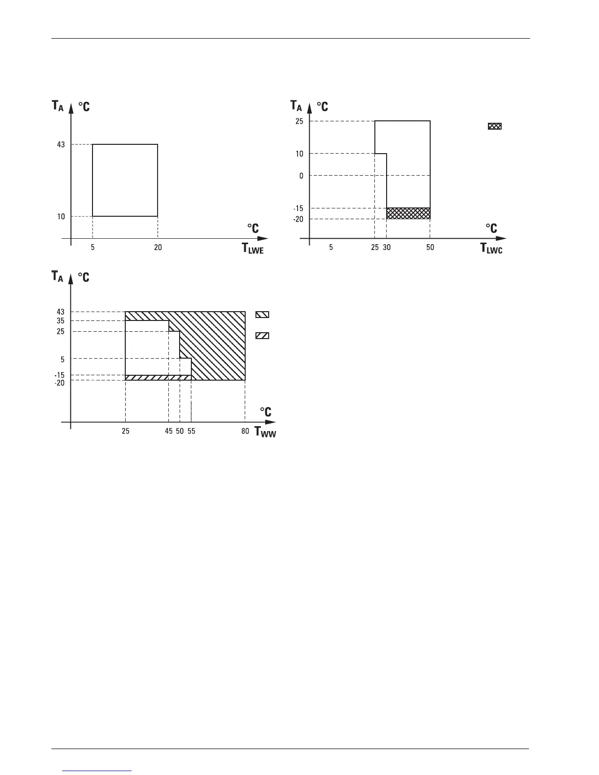
10.2.1 Characteristic curves for operating modes in 6-8 kW systems
Fig.10-1 Operating mode room cooling Fig.10-2 Operating mode room heating
T
A
External temperature
T
LWE
Temperature of discharge water at vaporiser
T
LWC
Temperature discharge water at the capacitor
T
WW
Hot water temperature
Area without hatching
Operation only with heat pump
Area A
Operation only with Booster Heater (EHS)
Area B
Operation with Booster Heater (EHS) and Backup Heater (BH)
Area C
Operation only with Backup Heater (BH)
Fig.10-3 Operating mode water heating
C



 To Next Page