www.rotexautomation.com
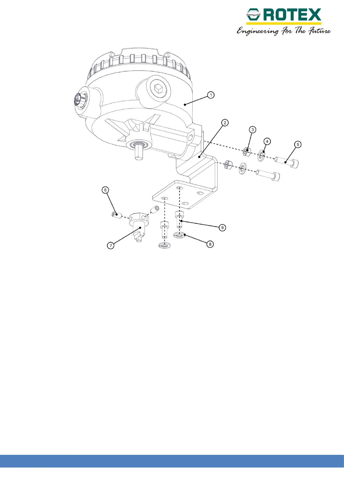
Figure 10: Attaching coupling and bracket to Remote unit
Mounting Instructions :
11. Attach the mounting bracket to the Remote unit using the Hardware items indicated in the
figure 10 above.
12. Attach the coupling securely using grub screws as indicated in the figure above.
13. The assembly is then mounted on the actuator (refer figure 11 below) while taking care that
the shaft enters in the slot of the actuator pinion.
14. Assembly of Remote unit and actuator should allow the play between shaft and pinion and
never between actuator body and bracket.
15. Secure the bolts tightly and proceed for calibration.
 Loading...