EasyManuals Logo

Rotex Posidapt Series User Manual

Rotex Posidapt Series
131 pages
To Next Page IconTo Next Page
To Previous Page IconTo Previous Page
Page #42 background imageLoading...
Page #42 background image
RTX-IOM-PRODUCT-YY
Page 42 of 131
www.rotexautomation.com
Table 6:
Sr. No.
Part description
Quantity
Note
1
Std Mounting bracket
1
Refer figure 9
2
Linear scale assembly
1
As shown in figure 1
3
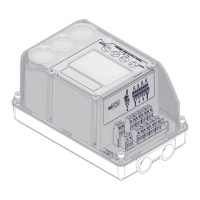
Remote mount Unit
2
Refer figure 9
4
Control Valve
2
Refer figure 9
Mounting Instructions :
Assemble the linear scale assembly as shown in the figure 1.
Attach the mounting bracket to the Remote unit.
Fix the Remote Unit along with the mounting bracket at the centre of the control valve
depending on the stroke of the control valve.
Insert the shaft in the slot of the scale and lock it using the locking screw.
Make sure that the scale is horizontal before calibrating the positioner.
Secure the bolts firmly and proceed for calibration.
Questions and Answers:

Question and Answer IconNeed help?

Do you have a question about the Rotex Posidapt Series and is the answer not in the manual?

Rotex Posidapt Series Specifications

General IconGeneral
BrandRotex
ModelPosidapt Series
CategoryValve Positioners
LanguageEnglish