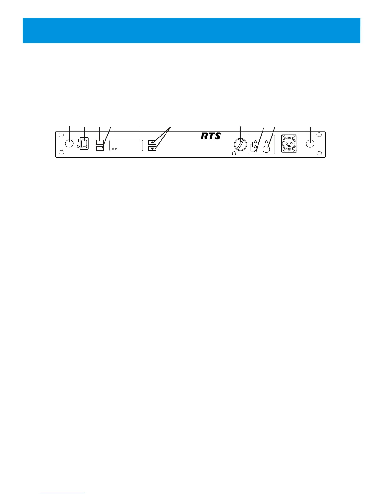
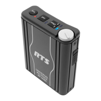
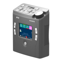
1. Power on/off switch – turns the power on/off to the
BTR-240.
2. <MENU> button – used to navigate the menu options on
the LCD.
3. <SET> button – used to navigate the menu and select
options on the LCD.
4. Backlit Graphics LCD (liquid crystal display).
5. <UP> and <DOWN> buttons – used to navigate the
menu options on the LCD.
6. <VOLUME> control knob – controls the volume for the
local headset.
7. <CHANNEL SELECT> button – controls the intercom
channel to which the local headset is connected. Each
press of the button changes the connection and cycles
between: Intercom 1, Intercom 2, and both. The
corresponding LEDs will illuminate.
8. <TALK> button – press to enable/disable the audio path
from the local headset. The green LED above the <TALK>
button will illuminate when active.
9. Local Headset Connector – standard 4-pin XLR
connector. Male XLR connector for Telex units, female
XLR connector for RTS units. A dynamic or electret
headset microphone is automatically detected by the base
station and a bias voltage is supplied if necessary.
10. Antenna Mount Knockouts – remove as desired to
mount the antennas on the front panel instead of the rear
panel via coaxial cables.
Section 2 - BTR-240 Base Station
2-1
TALK
CHANNEL
SELECT
1
2
VOLUME
BTR-240
POWER
menu
set
AuxOut:1&2G
1
2
1
3
4
6
7
5
8 9
10
AuxIn:1&2L
RF Ch: 6 2W:1&2
Assoc: 0 4W:1&2
10
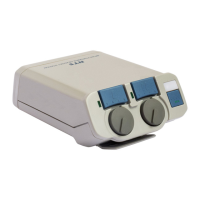
Figure 2-1
BTR-240 Front View
Controls and Connections - Front Panel