Hardware Installation and Reference Guide Product Overview
37
Back Panel
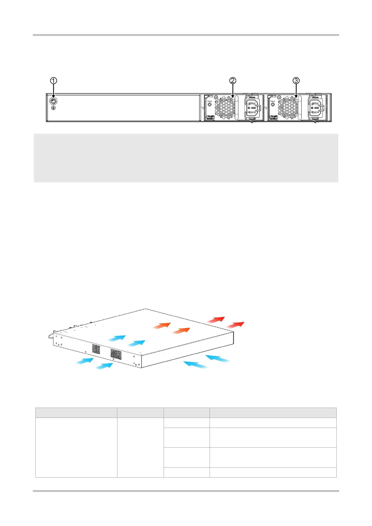
Figure 1-39 Back Panel of RG-S5310-48GT4XS-P-E
1. Grounding Stud
2. Power Supply Module Slot 1 (A filler panel is required if the
slot is vacant.)
3. Power Supply Module Slot 2 (A filler panel is required if the
slot is vacant.)
Power Supply
The RG-S5310-48GT4XS-P-E switch supports dual power supply modules. See Chapter 1.13 for details about the power supply modules.
The switch can be powered on by either one power supply module or dual power supply modules. If both power supply modules are
used, the switch works in the power redundancy mode.
Cooling
The RG-S5310-48GT4XS-P-E switch adopts a left-to-right and front-to-right airflow to ensure normal operation. Maintain a minimum
clearance of 100 mm (3.94 in.) around the device for air circulation.
Figure 1-40 Airflow Direction
LED
System is not powered on.
System is being initialized. Continuous blinking
indicates a fault.
System is operating normally.
 Loading...