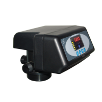
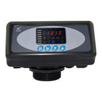
MODEL 53515/53615/63515/63615/73515/73615
24
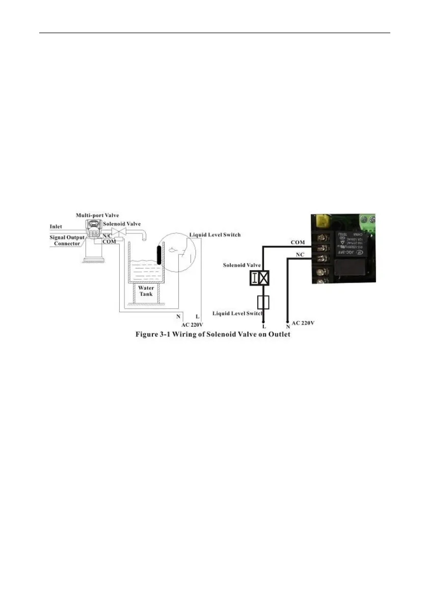
A. Signal Output Connector
1).Control Outlet Solenoid Valve(Set b-01)
①Solenoid valve on outlet controls the water level in brine tank.
Instruction: If system strictly requires no hard water flowing from outlet in
regeneration cycle (Mainly for no hard water flows out when valve is
switching. The control valve turns to or valve in backwash or brine
drawing and other regeneration status, there is no hard water flowing out
from outlet automatically.), a solenoid valve could be installed on outlet,
and the wring refers to Figure 3-1.
Function:
When valve is in service status, if soft water tank is short of water,
solenoid valve will open to supply soft water, but if water tank has
enough water, solenoid valve will close, so no soft water supplied to the
tank.
When the valve is in backwash or other regeneration status, there is
no signal output. So solenoid valve will close, and no raw water flows
into soft water tank.
②Control Inlet Solenoid valve (Set b-02)
Instruction: When inlet pressure exceeds 0.6MPa, install a solenoid
valve on inlet. Control mode is b-02. Pressure is relieved when valve
switch, the wiring refers to Figure 3-2. As Figure 3-3 shows, it also can
use the pressure relief connector to work.