MODEL 63504-F63C1/63604-F63C3/73504-F68C1/73604-F68C3
19
Mode 01: Signal turn on start of
regeneration and shut off end of
regeneration. (Connection refer
to the Figure P5)
Mode 02: Signal available only
intervals of regeneration cycles
and in service. (Connection refer
to the Figure P5)
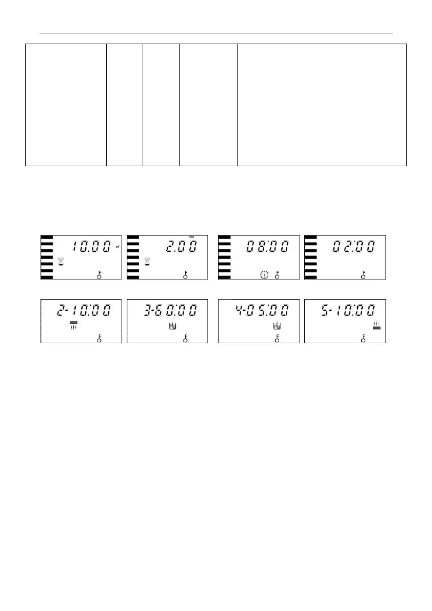
B. Process Display
Figure A Figure B Figure C Figure D
Figure E Figure F Figure G Figure H
Illustration:
In Service status, the figure shows A/B/C/D; In Backwash status, it
shows figure E/C; In Brine& Slow Rinse status, it shows F/C; In Brine
Refill status, it shows figure G/C; In Fast Rinse status, it shows figure
H/C. In each status, every figure shows 15 seconds.
Above displays are taking the Meter Type for example. For the Time
Clock Type, it shows the rest days or hours, such as 1-03D or 1-10H.
The display screen will only show “-00-” when the electrical motor is
running.
The time of day figure“” flash continuously, such as “12:12” flash,
indicates long outage of power. It reminds to reset the time of day.