12
LOC, IDLE STATE
This message will be displayed when input 24 is
activated, the door is fully closed (on the closed limit
switch) and the Digital Gateway programmed for LOC.
The Digital Gateway will be inactive and no inputs will
operate the door. (See Figure 16.)
LOC
A0500027
Figure 16
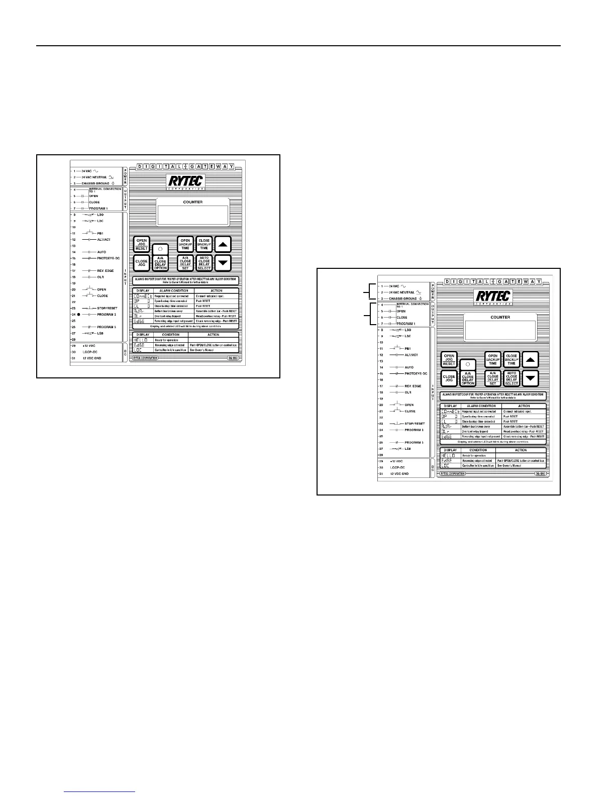
POWER
The Digital Gateway operates at 24 vac. Power is
applied through terminals 1, 2 and 3. Terminal 1 is 24
vac high side, terminal 2 is 24 vac low side and
terminal 3 is ground. (Figure 17.)
OUTPUTS
The 3 triac outputs of the Digital Gateway share a
common power source which is terminal 4. Terminal 4
is internally connected to the 24 vac power source.
Terminal 5 is the open output, supplying power to the
open contactor. Terminal 6 is the close output, supply-
ing power to the close contactor. Terminal 7 is the
Program 1 output. It can be used to power a relay
which can be used for a variety of things. (See
OPTIONAL PROGRAMS on page 13.)
An RC network and MOV are connected across each
output for noise suppression. An external MOV is
recommended across any contactor coil or solenoid
coil. The maximum rating for each output is 1-amp
inductive continuous. (See Figure 17.)
Figure 17
OUTPUTS
 Loading...