REPAIR GEAR POWER TRAIN
2/12/97 5 - 25
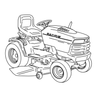
1. Remove brake assembly (A) (see previous
procedure). Remove sixteen transaxle housing
socket head screws (B).
2. Carefully separate transaxle housing case. Remove
upper case from lower case assembly.
3. Inspect overall condition of transaxle without
removing any components. Visually target worn or
damaged parts for replacement.
4. Remove most of the grease without removing any
components.
B
A
Upper Case
Half
Lower Case
Half
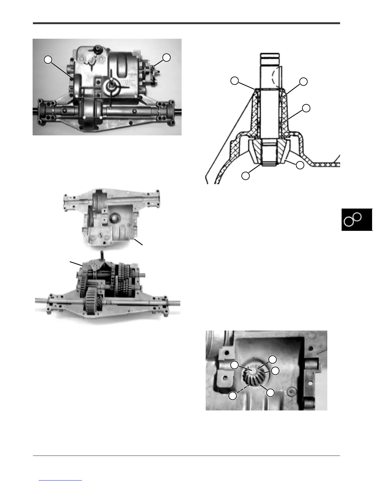
Input Shaft & Pinion Gear Inspection:
1. Visually check overall condition of assembly,
including the key and keyway, and the drive
sheave hub keyway.
2. Check condition of pinion gear (D) - look for wear,
pitting, broken teeth, etc.
3. Grasp the input shaft and try to rock it left or right
inside case housing. If movement is noticeable,
replace needle bearing (B and C).
4. Use a feeler gauge to measure clearance between
pinion gear (D) and snap ring (E):
Clearance . . . . . . . . . . .0.127 mm (0.005 in.) or less.
5. If clearance is excessive, shim thickness (A) needs
to be changed or worn components must be
replaced.
Input Shaft/Pinion Gear Disassembly:
1. Remove snap ring (E), bevel pinion gear (D), small
washer (F), and large washer (G) from input shaft
(K) inside upper case half.
E
D
B
C
A
E
D
G
F
K
www.servicemanualall.com
 Loading...