11
© 2015 SafeLine and all the SafeLine products and accessories are copyrighted by law.
MX3 v1.06 EN
Installation
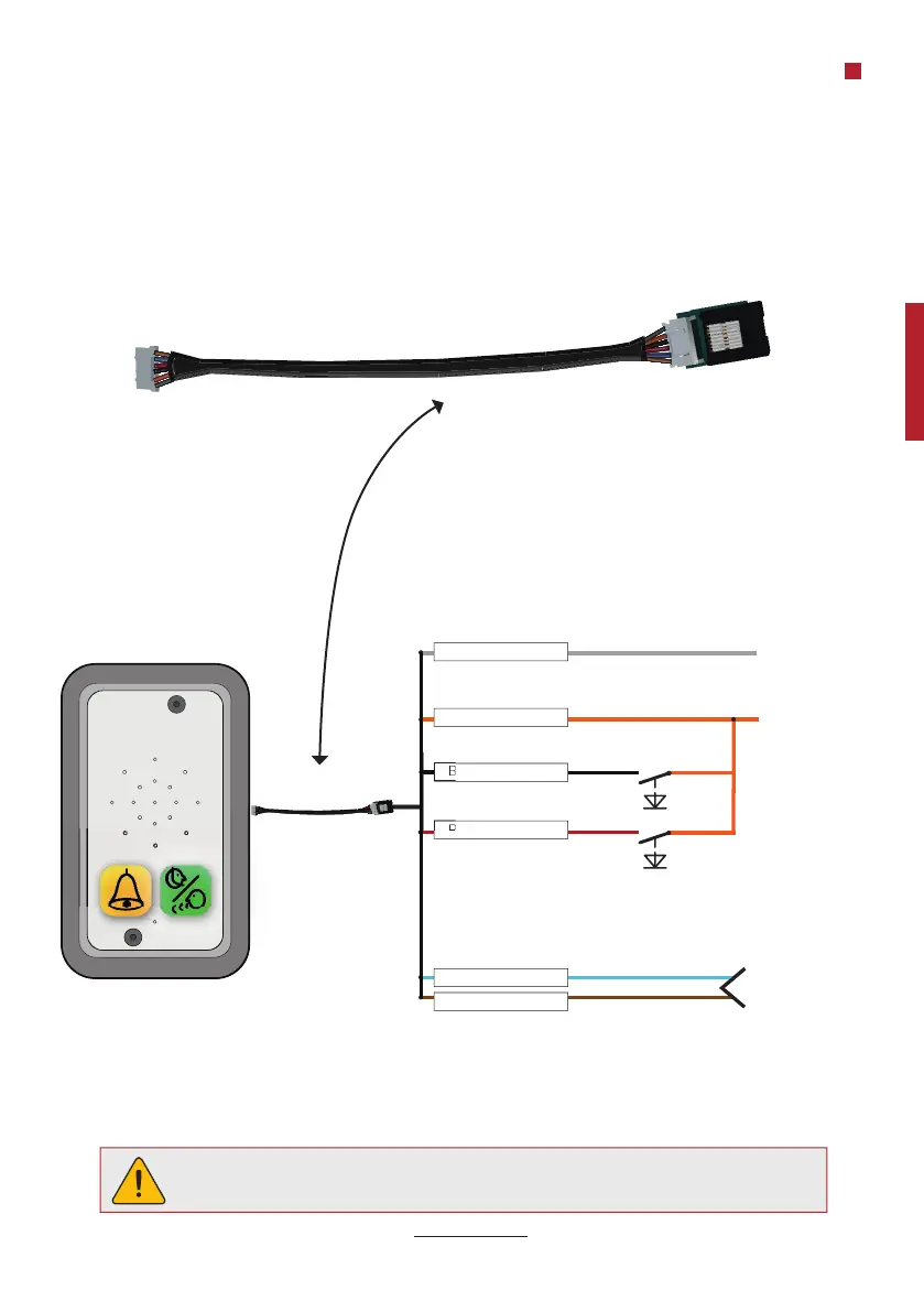
WIRING DIAGRAM, WHEN UPDATING TO MX3 FROM MX2
NOTE!
Unconnected cables must be isolated in order to avoid short circuiting.
Colours when using fl at cable
Voltage supply
0 V
Additional input
(fi lter)
Alarm button
Telephone line in
GRAY
BLACK
RED
BLUE
BROWN
ORANGE
Voltage supply
+10 - 30 V
When updating to MX3 from MX2, the RS2 cable kit is required (RJ45 to 6 pin connector).