6101
6101
6101
6101 Belt
Belt
Belt
Belt Scale
Scale
Scale
Scale Integrator
Integrator
Integrator
Integrator Operating
Operating
Operating
Operating and
and
and
and Service
Service
Service
Service Manual
Manual
Manual
Manual
14
Chapter
Chapter
Chapter
Chapter 2
2
2
2 Integrator
Integrator
Integrator
Integrator Installation
Installation
Installation
Installation
2.1
2.1
2.1
2.1 General
General
General
General
This chapter contains the information about the installation procedures, hardware
configuration and intial programme of 6101 integrator. During intial programme, operator
must input necessary conveyor and belt scale data. After data input, integrator can proceed
auto zero, span calibration.
2.2
2.2
2.2
2.2 6101
6101
6101
6101 Integrator
Integrator
Integrator
Integrator Installation
Installation
Installation
Installation
The 6101 integrator must be installed indoors, not be exposed to excessive vibration, heat or
moisture.
The panel mount integrator should be installed in a control panel. After installation,
dustproof measures should be taken for the front panel of the integrator and the control
cabinet. (figure 2-2)
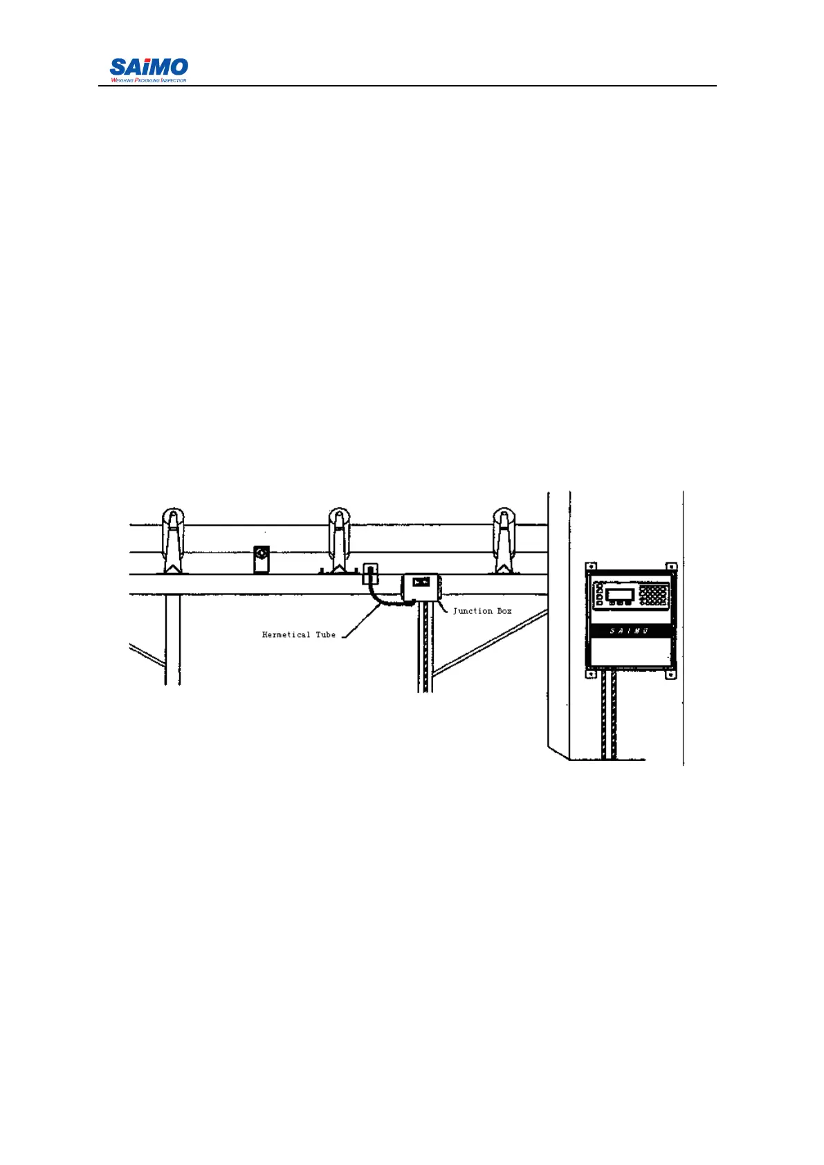
Figure 2- 1 Scale bridge installation illustration
2.2.1
2.2.1
2.2.1
2.2.1 Mounting
Mounting
Mounting
Mounting
The 6101 field mount feeder controller can be vertically secured to the rigid and flat wall
through the 4 mounting holes at the back of the enclosure. Care should be taken to insure the
mounting surface is flat so as not to twist or warp the fiberglass enclosure when tightening
the mounting holes.
The 6101 panel mount integrator should have a clearance of at least 5cm at the top and
bottom to allow air circulation. In case that the integrator must be positioned under the heat
sources, proper space around the integrator should be reserved. Sufficient space should be
kept behind the integrator to facilitate wiring and changing fuse. The side clearance should
be easy for securing the holding brackets after the 6101 has been put in place. Disconnect
power supply from the integrator when mounting the bracket. From the back, insert the