6101
6101
6101
6101 Belt
Belt
Belt
Belt Scale
Scale
Scale
Scale Integrator
Integrator
Integrator
Integrator Operating
Operating
Operating
Operating and
and
and
and Service
Service
Service
Service Manual
Manual
Manual
Manual
20
A . C ontrarotate bolt mounted at the left lower corner, open the door.
B . P ut power supply cable into tube at the right of housing bottom. (See figure 2-2).
C . Connect safe ground wiring plate located on the one side of chassis.
D . C onnect fire wire to L.
E . C onnect zero wire to N.
F
.
Close front chassis cover, then contra rotate the bolt at the left lower corner till cover is
locked, validation gate is locked.
2.
2.
2.
2. 2
2
2
2 .
.
.
. 4
4
4
4 Input voltage setup
Warning
Operated by qualified service engineer only.
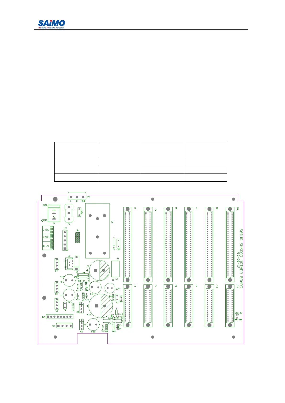
1. AC power supply selection switch S2, S3 located at the left upper section of main board
(figure 2-5).
AC input
voltage
F use F1 ( SB ) S 2 setup S 3 setup
110 2 A 110 -
220 2A 220/240 220
240 2 A 220/240 240
Figure 2- 5 6101 integrator mother board