4.2 Battery connection
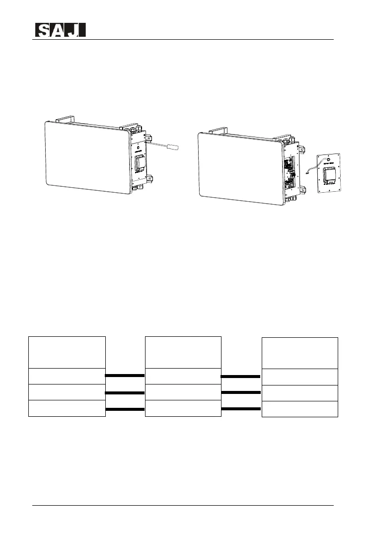
Make sure that the DC switch is OFF, remove the right wiring cover screws
and pull out the BMS switch cable then place the cover aside. Unplug the
battery switch cable carefully during dismantling.
Figure 4.2 Removing wiring cover
Lead power cables through the waterproof glands of the inverter and B1
respectively, make sure the cables are connected correctly (BAT+ of
inverter to BAT+ of B1, BAT- of inverter to BAT- of B1 and COMM of inverter
to COMM of B1, refer to wiring overview below). Do not reverse the positive
and negative terminals. Recommended DC cable conductor core section is
25mm
2
.
Wiring overview between battery and inverter
Figure 4.3 Single battery connection

 Loading...